Werbung
Continuity Testers
MEGGER
Safety warnings and precautions must be read and
understood before the instrument is used. They must be
observed during use.
The circuit under test must be switched off, de -
energised and isolated before Insulation or Continuity
tests are made.
The test button must not be held down while connecting
the test leads or while changing ranges. (May cause
'Live Circuit Warning' to become inoperable).
The Voltage warning does not function if OFF or
is selected.
During an insulation test, connections must not be
touched.
After insulation tests, capacitive circuits must be allowed
to discharge before disconnecting the test leads.
Test leads, prods and crocodile clips must be in good
order; clean, and with no broken or cracked insulation.
Replacement fuses must be of the correct size, type and
rating.
THE INSTRUMENTS MUST ONLY BE USED BY SUITABLY TRAINED AND COMPETENT
Caution: risk of electric shock
Caution: refer to accompanying notes
Equipment protected throughout by Double Insulation (Class II)
Equipment complies with relevant EU Directives
Insulation &
®
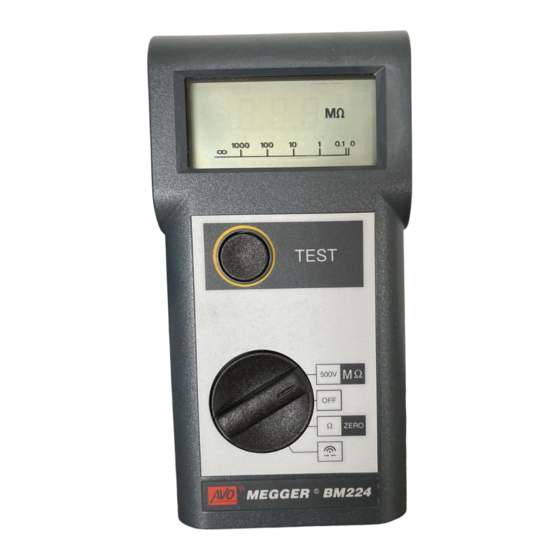
BM220 Series
User Guide
Guide de l'utilisateur
Gebrauchsanleitung
Guía del Usuario
SAFETY WARNINGS
NOTE
PERSONS
Symbols used on the instrument:
.
Werbung
Inhaltsverzeichnis

Inhaltszusammenfassung für Megger BM220 serie
- Seite 1 Insulation & Continuity Testers ® MEGGER BM220 Series User Guide Guide de l’utilisateur Gebrauchsanleitung Guía del Usuario SAFETY WARNINGS Safety warnings and precautions must be read and understood before the instrument is used. They must be observed during use. The circuit under test must be switched off, de - energised and isolated before Insulation or Continuity tests are made.
-
Seite 2: Display Features
Leads Low Battery DISPLAY FEATURES Nulled High 1000V Voltage 100 M 10 M Fuse Default Ruptured Voltage 100k All variants of the BM220 series of instruments have the following features: 1mA Insulation test current 200mA Continuity test with lead zeroing facility Combined curved Analogue / Digital display Continuity Beeper Auto shut off... -
Seite 3: Specification
Insulation Testing Turn the instrument ‘On‘ by selecting the MΩ range. Connect the test probes to the isolated circuit under test. Press and hold the push button; the display shows the insulation value.The reading will remain displayed for a few seconds after the push button is released. - Seite 4 will sound on all switch positions except ‘OFF‘ and . All selected tests will be inhibited except for Insulation tests, which will remain available until the voltage exceeds 55 V. (BM224 will beep and display a flashing ‘V’. Testing is inhibited). Default Voltmeter Ranges: 25V - 450V a.c.
- Seite 5 Approved Repair Companies. A number of independent instrument repair companies have been authorised for repair work on most Megger Instruments, using genuine Megger spare parts. Consult the Appointed Distributor / Agent regarding spare parts, repair facilities, and advice on the best course of action to take.
- Seite 6 Fax: +33 (1) 43.02.16.24 This instrument is manufactured in the United Kingdom. The company reserves the right to change the specification or design without prior notice. Megger is a registered trademark. Part No. 6172-231 - Edition 9 - Printed in England - 09HH...
- Seite 7 Guide Utilisateur AVERTISSMENTS RELATIFS A LA SECURITE • Le circuit à tester doit être coupé, désexcité et isolé avant d’entreprendre les essais d’isolement ou de continuité. • Le bouton d’essai ne doit pas être pressé pendant le branchement des câbles d’essai. •...
- Seite 8 maintenu, la tonalité cesse après quelques secondes et la valeur de la résistance est affichée. Les résistances supérieures à 5Ω sont signalées par une tonalité intermittente. Essai d’isolement Mettre l’instrument en service “ON” en sélectionnant la gamme MΩ. Brancher les sondes d’essai sur le circuit isolé à tester. Presser et tenir appuyé...
-
Seite 9: Sicherheitshinweise
Gebrauchsanleitung SICHERHEITSHINWEISE • Der geprüfte Stromkreis muß ausgeschaltet, entladen und isoliert werden, bevor mit der Isolierungs- oder Durchgängigkeitsprüfung begonnen wird. • Die Prüftaste darf beim Anschluß der Prüfkabel nicht gedrückt werden. • Die Spannungsmeldung funktioniert nicht, wenn die Stellung ‘OFF‘ oder gewählt wird. - Seite 10 Isolierprüfung Instrument durch Wählen des Bereichs MΩ einschalten (ON). Prüfspitzen an den zu prüfenden isolierten Stromkreis anschließen. Taste drücken und festhalten. Auf der Anzeige wird der Isolierwert dargestellt. Nach Loslassen der Taste bleibt der Wert einige Sekunden lang stehen. Als zusätzliche Sicherheitsvorrichtung blinkt bei Instrumenten mit einem Bereich von 1000 V vor der Prüfung das Symbol 1000V...
-
Seite 11: Avisos De Seguridad
Guía del Usuario AVISOS DE SEGURIDAD • El circuito en prueba deberá ser desconectado, desenergizado y aislado antes de efectuar pruebas de aislamiento o continuidad. • El botón de prueba no debe ser mantenido pulsado mientras se conectan los conductores de prueba. •... - Seite 12 cesa después de unos segundos y se visualiza el valor de la resistencia. Una resistencia superior a 5Ω es indicada al sonar un `bip' sonoro intermitente. Prueba de aislamiento Conmute el instrumento seleccionando la gama MΩ. Conecte las sondas de prueba al circuito aislado en prueba. Pulse y retenga el botón;...


