Inhaltsverzeichnis
Werbung
Verfügbare Sprachen
Verfügbare Sprachen
Quicklinks
Aloys F. Dornbracht GmbH & Co. KG Armaturenfabrik Köbbingser Mühle 6 D-58640 Iserlohn
Telefon +49 (0) 23 71 - 433 0 Fax +49 (0) 23 71 - 433 232 E-Mail mail@dornbracht.de www.dornbracht.com
DE
Dornbracht Hotline Technische Beratung
E-Mail tservice@dornbracht.de
AT
Dornbracht Austria GmbH
BE, LU
Gils & Gils BVBA
CH
Sadorex Handels AG
CZ, SK
agentura kramárová
ES
Dornbracht España S.L.
FR
Dornbracht France SARL
GR
Kallergis S.A.
HU
Z-A DESIGN Stúdió Kft.
IE
Aquality Ltd.
IT
Dornbracht Italia s.r.l.
LB
Naji Kanafani & Fils
LT, EE, LV
Arunas Jazukevicius
MT
Creations The Ultimate in Bathroom Elegance Ltd.
NL
Dornbracht Nederland B.V.
PL
Honorata Broniowska
PT
AzurAmbiente Lda.
RO
Reallize Consult SRL
RU
OSA GmbH & Co. KG
SI, HR
Irena Jesen‰ek
SRB, BiH, MNE, MK
Nenad Djukic
TR
Kent Yapi Sanayi
UA
Alexej Khelemendik
UK
Dornbracht UK Ltd.
América Central
Dornbracht México S.A. de C.V.
US, CA
Dornbracht Americas Inc.
Far East, Australasia, India
Dornbracht Asia Pacific Ltd.
Shanghai
Dornbracht (Shanghai) Commercial Ltd.
AE, BH, EG, IQ, IR, JO, KW,
Dornbracht International Holding GmbH
LB, OM, PK, QA, SA, SY, YE
01.03.72.971.15/10.2008 // headline:Werbeagentur . Iserlohn
Service
Pflege- und Wartungs tips entnehmen Sie bitte der beiliegenden Broschüre. // Verzorgings- en onderhoudstips
vindt u in de bijgevoegde brochure. // Vous trouverez des conseils d'entretien et de maintenance dans la brochure
ci-jointe. // Tips on care and maintenance for your new product can be found in the Finished Excellence brouchure. //
Per consigli sulla cura e manutenzione si rimanda all'allegato opuscolo. // Sugerencias para la conservación y el
mantenimiento puede tomarlas del folleto adjunto.
Installation instructions
Montageaanwijzing
Instructions de montage
Istruzioni di montaggio
Tel. +49 (0)2371-433-480
Instrucciones de montaje
Fax +49 (0)2371-433-175
Assembly Instructions
Tel. +43 (0)2236-677360
Monteringsanvisning
Tel. +32 (0)3-235 636 6
MontáÏní návod
Tel. +32 (0)3-235 252 1
Instrukcja monta˝u
Tel. +41 (0)62-787 20 30
Tel. +420 233 372 617
Tel. +34 93-272 391 0
Tel. +33 (0)1 40 21 10 70
Tel. +30 210 515 6756
Tel. +36 1 242 33 89
Tel. +353 45901210
Tel. +39 02 81 83 43 1
Tel. +961 1 307 400
Tel. +370 686 303 13
Tel. +356 2141 1541
Tel. +356 2141 7616
Tel. +31 (0)10 5243400
Tel. +48 (0)95-728 261 7
Tel. +351 219 498 210
Tel. +40 21 528 03 86
Tel. +49 (0)2371-233 11
Tel. +386 (0)128 314 67
Tel. +381 (0)65 2000 977
Tel. +90 216-363 224 1
Tel. +38 (0)44-244 7682
Tel. +44 (0)2476-717 129
Tel. +52 (55) 5343 9246
Tel. +52 (55) 5343 8450
Tel. +1 770-564-3599
Tel. +1 800-774-1181
Tel. +852 250 562 54
Montageanleitung
Tel. +86 (0)21-6360 6930
Tel. +86 (0)21-5150 6775
20 710 XXX // 20 712 XXX // 20 713 XXX // 20 815 XXX // 24 610 890
Tel. +971 4 - 3350731
Haftung nur bei Montage durch einen Fachinstallateur // Warranty is void unless
installed by a professional plumber // Aansprakelijkheid uitsluitend bij montage door een
erkend installateur // Notre responsabilité n'est engagée que si le montage est effectué
par un installateur spécialisé // La responsabilità verrà assunta solo se il montaggio è stato
compiuto da un installatore qualificato // Sólo se asume responsabilidad si lo instala un
especialista // Warranty is void unless installed by a professional plumber // Garantin gäl-
ler endast när montering utförs av behörig installatör // Záruka pouze pfii montáÏi kvalifi-
kovan˘m instalatérem // Gwarancja tylko przy monta˝u przez wyspecjalizowanego
instalatora // Материальная ответственность изготовителя только при монтаже
квалифицированным сантехником //
с
ук
о о
у
Werbung
Inhaltsverzeichnis

Verwandte Anleitungen für Dornbracht 20 710 series


Inhaltszusammenfassung für Dornbracht 20 710 series
- Seite 1 Aloys F. Dornbracht GmbH & Co. KG Armaturenfabrik Köbbingser Mühle 6 D-58640 Iserlohn Installation instructions Telefon +49 (0) 23 71 - 433 0 Fax +49 (0) 23 71 - 433 232 E-Mail mail@dornbracht.de www.dornbracht.com Montageaanwijzing Instructions de montage Istruzioni di montaggio Dornbracht Hotline Technische Beratung Tel.
-
Seite 2: Montage
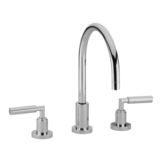
1.0 LIEFERUMFANG 3.0 MONTAGE 20 710 890 Lochbohrung: 32 mm Designelemente nicht im Lieferumfang. Maximale Stärke der Hahnlochbank: 35 mm Abmessungen und Ausladung entnehmen Sie bitte 2.0 BETRIEBSBEDINGUNGEN den Maßzeichnungen. Empfohlene Vorlauftemperatur 65° C Maximale Vorlauftemperatur 80° C O-Ring des Befestigungssatzes in die Nut des G 3/4 Mindestfließdruck 1 bar... - Seite 3 Montieren Sie die Ablaufgarnitur. Zugstange über 20 815 890 das Gelenkstück mit der Kugelstange verbinden. Abb. 4 G 3/4 G 1/2 24 610 890 Abb. 4 G 3/4 G 1/2 Serien: TARA, TARA CLASSIC Rosette mit O-Ring auf das Seitenventil schrauben. Hülse bis zum Anschlag auf das Oberteil schrauben.
-
Seite 4: Omvang Van De Levering
1.0 OMVANG VAN DE LEVERING 3.0 MONTAGE 20 710 890 Opening = 32 mm Design-elementen behoren niet tot de omvang Maximale dikte van de geperforeerde plaat van de levering. van de kraan: 35 mm 2.0 BEDRIJFSVOORWAARDEN Zie voor de afmetingen en de sprong de Aanbevolen voorlooptemperatuur 65°C tekeningen op schaal. - Seite 5 Monteer de afloopgarnituur. Verbind de trekstang via 20 815 890 het scharnierstuk met de kogelstang. Zie afb. 4 G 3/4 G 1/2 24 610 890 afb. 4 G 3/4 G 1/2 Series: TARA, TARA CLASSIC Schroef rozet met O-ring op de zijklep. Schroef de huls tot aan de aanslag op het bovenstuk.
- Seite 6 1.0 PIECES LIVREES 3.0 MONTAGE 20 710 890 Forure: 32 mm Les éléments de design ne font pas partie des Epaisseur maximale de la paroi perforée pièces livrées. pour le robinet: 35 mm Les dimensions et la saillie sont indiquées sur les 2.0 CONDITIONS DE FONCTIONNEMENT dessins cotés.
- Seite 7 Bidet avec bec déverseur fixe 20 815 890 24 610 890 Montage comme décrit plus haut – lors du positionnement du bec déverseur, l’aplatissement du tenon embrochable doit être orienté vers la vis. Le bec déverseur, après avoir été serré à bloc, ne doit plus pouvoir être tourné.
-
Seite 8: Parts Supplied
232 psi Place the flat rubber washer into the cut-out of mounting kit bracket. Align hole in mounting bracket At operating pressure exceeding 72 psi, Dornbracht with threaded rod and slide up to the underside of 20 712 890 recommends that a pressure reducer be installed in deck. - Seite 9 Bidet with fixed spout: 20 815 890 24 610 890 Loosen the allen screw with the provided allen key. Insert the spout and tighten the allen screw. When tightening make sure that the flat area on the plug faces the allen screw. The spout may not move after tightening.
-
Seite 10: Installation
1.0 PARTS SUPPLIED 3.0 INSTALLATION 20 710 890 Hole diameter: 32 mm Design elements not included in set. Maximum shelf thickness: 35 mm Please refer to the scale drawings for sizes and projection. 2.0 OPERATING CONDITIONS G 3/4 Place the mounting set's o-ring into the outlet's Recommended feed temperature 65°... - Seite 11 Bidet outlet with fixed spout. 20 815 890 24 610 890 Assembly as above – when inserting the spout, the flat area on the plug pin must point towards the screw. The spout may not move after tightening. G 3/4 Assemble the pop-up waste set.
-
Seite 12: Entità Di Fornitura
1.0 ENTITÀ DI FORNITURA 3.0 MONTAGGIO 20 710 890 Foro di montaggio: 32 mm Finiture non comprese nell’entità di fornitura. Spessore massimo del piano di montaggio: 35 mm 2.0 CONDIZIONI D’ESERCIZIO Per le dimensioni e il sbraccio vedi i disegni quotati. Temperatura di mandata consigliata 65°C Montare l’anello O del kit di fissaggio nella scanala-... - Seite 13 Bocca bidet fissa. 20 815 890 24 610 890 Montaggio come sopra - nel montare la bocca, il lato appiattito della spina deve indicare in direzione della vite. Dopo averla fissata, la bocca non deve più potersi girare. G 3/4 Montare lo scarico.
-
Seite 14: Montaje
1.0 ALCANCE DEL SUMINISTRO 3.0 MONTAJE 20 710 890 Orificio: 32 mm Elementos de diseño no incluidos en el Grosor máximo del orificio de montaje: 35 mm suministro. Para las medidas y la saliente véanse los planos de 2.0 CONDICIONES DE SERVICIO medidas. - Seite 15 Salida de bidé fija. 20 815 890 24 610 890 Montaje cómo arriba - al insertar la salida, el lado aplanado del perno insertable debe indicar hacia el tornillo. Después de apretar la salida, no debe ser posible girarla más. G 3/4 Montar el juego de evacuación.