Inhaltsverzeichnis
Werbung
Werbung
Inhaltsverzeichnis

Verwandte Anleitungen für Allnet ALL-MC115VDSL2


Inhaltszusammenfassung für Allnet ALL-MC115VDSL2
- Seite 1 ALL-MC115VDSL2 VDSL2 100 Mbit Mini Modem Master / Slave...
-
Seite 2: Foreword: Vdsl2 Solution
Since VDSL2 has the characteristic of higher bandwidth over shorter distances, the ideal architecture for Telcoms is to use fiber optic lines as the backbone and a VDSL2 line as the last mile into the home or office. With outstanding throughput, the ALL-MC115VDSL2 can complement a fiber network to offer the best solution for delivering Triple play(Video/Voice/Data) or home entertainment services. -
Seite 3: Safety Warnings
ALL-MC115VDSL2 Mini Modem Master/Slave Manual Safety Warnings For your safety, be sure to read and follow all warning notices and instructions before using the device. DO NOT open the device or unit. Opening or removing covers can expose you to dangerous high voltage points or other risks. -
Seite 4: Inhaltsverzeichnis
ALL-MC115VDSL2 Mini Modem Master/Slave Manual TABLE OF CONTENTS FOREWORD: VDSL2 SOLUTION .......................... 1 SAFETY WARNINGS .............................. 2 CHAPTER 1. UNPACKING INFORMATION ......................5 1.1 Check List ...................................... 5 CHAPTER 2. INSTALLING THE BRIDGE ......................6 2.1 Hardware Installation ..................................6 2.2 Pre-installation Requirements ................................ - Seite 5 ALL-MC115VDSL2 Mini Modem Master/Slave Manual 3.1 Front Panel ....................................12 3.2 Front Indicators .................................... 12 3.3 Rear Panel ....................................15 APPENDIX A: CABLE REQUIREMENTS ......................24 APPENDIX B: PRODUCT SPECIFICATION ......................27 APPENDIX C: TROUBLESHOOTING ........................29 APPENDIX D: COMPLIANCE INFORMATION ..................... 35 APPENDIX E: PERFORMANCE TABLE ......................
-
Seite 6: Chapter 1. Unpacking Information
2. Do not use sub-standard power supply. Before connecting the power supply to the device, be sure to check compliance with specifications. The ALL-MC115VDSL2 of the power supply at least use DC12V/1A. 3. Power supply included in package is commercial-grade. Do not use in industrial-grade applications. -
Seite 7: Chapter 2. Installing The Bridge
ALL-MC115VDSL2 Mini Modem Master/Slave Manual 4.If you would like to use the telephone, please purchase a suitable external splitter and install to the line port. Chapter 2. Installing the Bridge 2.1 Hardware Installation This chapter describes how to install the bridge and establishes network connections and may install the bridge on any level surface (e.g. -
Seite 8: General Rules
ALL-MC115VDSL2 Mini Modem Master/Slave Manual 2.3 General Rules Before making any connections to the bridge, please note the following rules: Ethernet Port (RJ-45) All network connections to the bridge Ethernet port must be made using Category 5 UTP or above for 100Mbps, Category 3, 4 UTP for 10Mbps. -
Seite 9: Connecting The Rj-11 / Rj-45 Ports
The line port has 2 connectors: RJ-45 and terminal block. It is used to connect from ALL-MC115VDSL2 (CO) using single pair phone cable to ALL-MC115VDSL2 (CPE) bridge side (point to point solution). Take note that ALL-MC115VDSL2 line port cannot be used at the same time. - Seite 10 RJ-11(VDSL2 Line port) use 24 ~ 26 gauge with twisted pair phone wiring, we do not recommend 28 gauge or above. Be sure phone wire has been installed before ALL-MC115VDSL2 powered on.
-
Seite 11: Vdsl2 Bridge Application
Every modular phone jack in the home can become a port on the LAN. Networking devices can be installed on a single telephone wire that can be installed within suitable distance (depends on speed) (Figure 2.6) Figure 2.6 ALL-MC115VDSL2 point to point application diagram... -
Seite 12: Chapter 3. Hardware Description
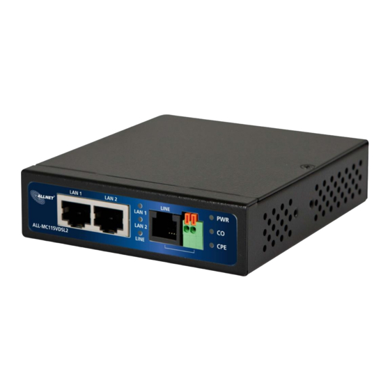
ALL-MC115VDSL2 Mini Modem Master/Slave Manual Chapter 3. Hardware Description This section describes the important parts of the bridge. It features the front panel, side panel and rear panel. ALL-MC115VDSL2 Outward... -
Seite 13: Front Panel
ALL-MC115VDSL2 Mini Modem Master/Slave Manual 3.1 Front Panel The figure shows the front panel. (Figure 3.1) Figure 3.1 Front Panel Tip: At a quick glance of the front panel, it is easy to determine if it has Ethernet signal from its RJ-45 port and if there is vdsl line signal on RJ-11 port. - Seite 14 ALL-MC115VDSL2 Mini Modem Master/Slave Manual 3.1 Frontseite Figure 3.1 Frontseite Tipp: Über die LED-Anzeige erkennen Sie, ob ein Ethernet-Signal an den RJ-45-Eingang anliegt, sowie ob die Verbindung für VDSL am RJ-11-Eingang synchron ist. Connectors Type Description LAN1 / LAN2 RJ-45 Schnittstelle für eine Ethernet-Verbindung.
-
Seite 15: Front Indicators
Note: Two Bridges connection may take within 3 minutes is normal, due to ALL-MC115VDSL2 to establish a link mechanism is auto-negotiation, with detects and calculate CO and CPE both PBO and PSD level as well as noise level ..and other argument etc. - Seite 16 ALL-MC115VDSL2 Mini Modem Master/Slave Manual 3.2 Frontanzeigen Der ALL-MC115VDSL2 besitzt 8 Frontanzeigen, die in der folgenden Tabelle erklärt werden. (Table 3-2) Color Status Descriptions On(Steady) Gerät ist an Stromzufuhr angeschlossen. Green (Power LED) Keine Stromzufuhr oder defekt. On(Steady) Stabile Ethernet-Verbindung.
-
Seite 17: Rear Panel
ALL-MC115VDSL2 Mini Modem Master/Slave Manual 3.3 Rear Panel The following figure shows the rear panel. (Figure 3.2) Figure 3.2 Rear Panel And the table shows the description. (Table 3-3) Table 3-3 Description of the bridge front connectors Connectors Type Description... -
Seite 18: Rückseite
ALL-MC115VDSL2 Mini Modem Master/Slave Manual 3.3 Rückseite Figure 3.2 Rückseite Connectors Type Description External Power Adapter: Input: AC 85~240Volts/50~60Hz Power DC Power Jack Output: DC 12V/1A DIP Switch 4 Pins DIP Switch Bietet 4 verschiedene Einstellungen für die Übertragung. Earthing strip Erdungsklemme, zum Schutz vor Stromschlag. - Seite 19 ALL-MC115VDSL2 Mini Modem Master/Slave Manual The following figure shows the DIP switch connection. By switching the transmission modes, you can obtain a best transmission mode to suit with phone line quality or distance or connectivity. (Figure 3.3) Figure 3.3 DIP switch setting The following is table of DIP Switch configuration.
- Seite 20 ALL-MC115VDSL2 Mini Modem Master/Slave Manual PIN1: ON: CO(Central Office) Mode or called Local Side, usually the CO device will be located at the data enter of enterprise to link to the backbone. OFF: CPE(Customer Premises Equipment) Mode or called Remote Side, usually the CPE side will be located at building, monitoring for car parks and train station as the long reach data receiver.
- Seite 21 PIN2: ON: High Band- Modus (500KHz to 30MHz), sendet über ISDN-Bandbreite (0 ~ 499KHz sind leer). OFF: Low Band-Modus (25KHz to 30MHz). Das ALL-MC115VDSL2 wird die Kabellänge automatisch erkennen und die Geschwindigkeit daran anpassen. Die VDSL2-Bandbreite erfasst 25KHz bis 30MHz.
- Seite 22 ALL-MC115VDSL2 Mini Modem Master/Slave Manual TIP(Reference Only): Interleave delay function is used in digital data transmission technology to protect the transmission against noise issue and data error. If during transit more than a certain amount of data has been lost then the data cannot be correctly decoded. Short bursts of noise on the line can cause these data packets to become corrupt and the bridge has to re-request data which in turn can slow down the overall rate at which data is transmitted.
-
Seite 23: Safety Caution
ALL-MC115VDSL2 Mini Modem Master/Slave Manual INP(Impulse Noise Protection): Impulse noise in multicarrier communication systems behaves effectively as a modulating signal that controls the first moment of the background Gaussian noise. The composite noise, which is the aggregate of the Gaussian noise and impulse noise, has a probability density function that is conditionally Gaussian with non-zero average, hence referred to as biased-Gaussian. - Seite 24 ALL-MC115VDSL2 Mini Modem Master/Slave Manual Grounding the ALL-MC115VDLS2 ALL-MC115VDLS2 is designed to enhance EMS performance by grounding. ALL-MC115VDLS2 come with for grounding the switches. For optimal EMS performance, connection of the left side of the ALL-MC115VDLS2 rear panel ground lug to the grounding point.
-
Seite 25: Appendix A: Cable Requirements
ALL-MC115VDSL2 Mini Modem Master/Slave Manual Appendix A: Cable Requirements Ethernet Cable A CAT 3~7 UTP (unshielded twisted pair) cable is typically used to connect the Ethernet device to the bridge. A 10Base-T cable often consists of four pairs of wires, two of which are used for transmission. The connector at the end of the 10Base-T cable is referred to as an RJ-45 connector and it consists of eight pins. - Seite 26 ALL-MC115VDSL2 Mini Modem Master/Slave Manual Figure A-2 Pin Assignments and Wiring for an RJ-45 Straight-Through Cable Figure A-3 Pin Assignments and Wiring for an RJ-45 Crossover Cable...
- Seite 27 ALL-MC115VDSL2 Mini Modem Master/Slave Manual In diesem Bild sehen Sie ein Musterbeispiel für ein verdrilltes VDSL-Kabel In this picture you can see a paradigm for twisted VDSL cable. Bitte beachten: Der Verbindungsaufbau sowie die Performance sind von der Verdrillungsqualität des Kabels abhängig.
-
Seite 28: Appendix B: Product Specification
ALL-MC115VDSL2 Mini Modem Master/Slave Manual Appendix B: Product Specification Key Features & Benefits Supports RJ-11/Terminal Block combo for Line port. Supports high bandwidth up to 100Mbps symmetric over Line ports Support long reach mode up to 3 km with 24 gauge phone wire ... - Seite 29 ALL-MC115VDSL2 Mini Modem Master/Slave Manual 1 x Power Jack RJ-45 (Ethernet): Category 3~7 UTP/STP Cable Connections: RJ-11 (VDSL2): Twisted Pair phone wire 1 x Power LED 2 x Link/Active Status for Ethernet port LED Indicators: 1 x Link LED for VDSL2 port...
-
Seite 30: Appendix C: Troubleshooting
ALL-MC115VDSL2 Mini Modem Master/Slave Manual Appendix C: Troubleshooting Diagnosing the Bridge’s Indicators The bridge can be easily monitored through its comprehensive panel indicators. These indicators assist the network manager in identifying problems the hub may encounter. This section describes common problems you may encounter and possible solutions. - Seite 31 ALL-MC115VDSL2 Mini Modem Master/Slave Manual VDSL Link cannot be established. 3. Symptom: Cause: VDSL setting failure or phone cable length is over the specification limit. 3.1 Please make sure that the phone wire must be connected between ALL-MC115VDLS2 (CO) and ALL-MC115VDLS2 (CPE) when both are power on. ALL-MC115VDLS2 (CO) will do link speed function depending on phone wire length, therefore if ALL-MC115VDLS2 (CO) can’t...
- Seite 32 ALL-MC115VDSL2 Mini Modem Master/Slave Manual wireline communications. Designed to support the wide deployment of triple play services such as voice, video, data, high definition television (HDTV) and interactive gaming, VDSL2 was intended to enable operators and carriers to gradually, flexibly, and cost-efficiently upgrade existing xDSL infrastructure.
- Seite 33 ALL-MC115VDSL2 Mini Modem Master/Slave Manual 5. Problem: What is SNR(Signal-to-Noise) Signal-to-noise ratio (often abbreviated SNR or S/N) is a measure used in science and engineering that compares the level of a desired signal to the level of background noise. It is defined as the ratio of signal power to the noise power.
- Seite 34 ALL-MC115VDSL2 Mini Modem Master/Slave Manual System Diagnostics Power and Cooling Problems If the POWER indicator does not turn on when the power cord is plugged in, you may have a problem with the power outlet, power cord, or internal power supply as explained in the previous section. However, if the unit power is off after running for a while, check for loose power connections, power losses or surges at the power outlet.
- Seite 35 ALL-MC115VDSL2 Mini Modem Master/Slave Manual Physical Configuration If problems occur after altering the network configuration, restore the original connections, and try to track the problem down by implementing the new changes, one step at a time. Ensure that cable distances and other physical aspects of the installation do not exceed recommendations.
-
Seite 36: Appendix D: Compliance Information
ALL-MC115VDSL2 Mini Modem Master/Slave Manual Appendix D: Compliance Information FCC Radio Frequency Interference Statement This equipment has been tested and found to comply with the limits for a computing device, pursuant to Part 15 of FCC rules. These limits are designed to provide reasonable protection against harmful interference when the equipment is operated in a commercial environment. - Seite 37 ALL-MC115VDSL2 Mini Modem Master/Slave Manual proper functioning of your equipment. If they do, you will be notified in advance in order for you to make necessary modifications to maintain uninterrupted service. This equipment may not be used on coin service provided by the telephone company. Connection to party lines is subject to state tariffs.
- Seite 38 ALL-MC115VDSL2 Mini Modem Master/Slave Manual WEEE Warning To avoid the potential effects on the environment and human health as a result of the presence of hazardous substances in electrical and electronic equipment, end users of electrical and electronic equipment should understand the meaning of the crossed-out wheeled bin symbol. Do not dispose of...
-
Seite 39: Appendix E: Performance Table
ALL-MC115VDSL2 Mini Modem Master/Slave Manual Appendix E: Performance Table Master Slave Configuration Speed in Mbps 93 / 40 ALL126AM2 ALL-MC115VDSL2 17a / Annex C / Filter Off / B43 93 / 40 ALL126AM2 ALL-MC115VDSL2 17a / Annex C / Filter Off / V43... - Seite 40 ALL-MC115VDSL2 Mini Modem Master/Slave Manual Test Environment: Test Items Descriptions VDSL2 Bridge CO Mode x 1 ALL-MC115VDLS2 CO Mode VDSL2 Bridge CPE Mode x 1 ALL-MC115VDLS2 CPE Mode Operation System Windows XP Ethernet Cable Cat 5e. UTP RJ-45 8P8C Ethernet Cable...
- Seite 41 ALL-MC115VDSL2 Mini Modem Master/Slave Manual (A). Spectrum: 25K~30MHz (US: Up Stream / DS: Down Stream) Cable Length Cable Length Cable Length US [Mbps] DS [Mbps] US [Mbps] DS [Mbps] US [Mbps] DS [Mbps] (meters) (meters) (meters) 28.58 26.87 2000 2.50 14.92...
-
Seite 42: Warranty
ALL-MC115VDSL2 Mini Modem Master/Slave Manual Warranty The original product that the owner delivered in this package will be free from defects in material and workmanship for one year parts after purchase. There will be a minimal charge to replace consumable components, such as fuses, power transformers, and mechanical cooling devices. - Seite 43 The safety advice in the documentation accompanying the products shall be obeyed. The conformity to the above directive is indicated by the CE sign on the device. The Allnet ALL-MC115VDSL2 conforms to the Council Directives of 2004/108/EC. This equipment meets the following conformance standards:...
- Seite 44 ALL-MC115VDSL2 Mini Modem Master/Slave Manual This declaration is made by ALLNET Computersysteme GmbH Maistraße 2 82110 Germering Germany Germering, 30.08.2013...