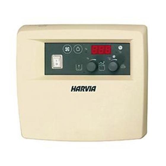
Harvia C105S Bedienungsanleitung
Vorschau ausblenden
Andere Handbücher für C105S:
- Bedienungsanleitung (12 Seiten) ,
- Bedienungsanleitung (56 Seiten)
Inhaltsverzeichnis
Werbung
Quicklinks
Werbung
Inhaltsverzeichnis

Inhaltszusammenfassung für Harvia C105S
- Seite 1 C105S Control unit Steuergerät 6 x 0,25 4 x 0,25 l=4 m 04042011...
-
Seite 2: Inhaltsverzeichnis
ContentS InhALt 1. ContRoL UnIt C105S ..........3 1. SteUeRGeRÄt C105S ..........3 1.1. General ............3 1.1. Allgemeines ............3 1.2. Technical Information ........3 1.2. Technische Daten ..........3 2. InStRUCtIonS FoR USe ...........4 2. BeDIenUnGSAnLeItUnG ...........4 2.1. Selecting presetting times and duration of preset time 2.1. -
Seite 3: Control Unit C105S
1. SteUeRGeRÄt C105S 1.1. General 1.1. Allgemeines The purpose of the C105S control unit is to control Mit dem Steuergerät wird der Elektrosaunaofen und an electric sauna heater and steamer, or a Combi der Verdampfer der Sauna oder deren Kombination, heater, which is their combined version. -
Seite 4: Instructions For Use
Fix: Press the overheat limit reset button. Figure 6. Check the wiring and connections from connectors 1 and 2 to the sensor. Behebung: Rücksetzknopf des Überhitzungsschutzes drücken. Abbildung 6. Verkabelung und Anschlüsse von den Anschlüssen 1 und 2 an den Fühlern prüfen. Humidity sensor’s temperature measuring circuit open. -
Seite 5: Selecting Presetting Times And Duration Of Preset Time
10. Indicator light glows, when fan is on 11. Die Kontrolllampe leuchtet, wenn die 11. Indicator light glows when sauna lights are on Beleuchtung eingeschaltet ist. 12. When indicator light is glowing humidity count 12. Wenn die Kontrolllampe leuchtet, zeigt die appears in screen Anzeige die Feuchtigkeit an. -
Seite 6: Instructions For Installation
3. InStRUCtIonS FoR InStALLAtIon 3. InStALLAtIonSAnLeItUnG The control unit should be Das Steuergerät wird au- mounted outside the steam ßerhalb der Saunakabine an room in a dry location (air einem trockenen Ort (Umge- temperature >+0 ºC). bungstemperatur >+0 °C). note! the control unit must Achtung! Das Steuergerät not be embedded in the wall darf nicht in der Wand ver-... -
Seite 7: Mounting The Sensors
KIP60E KIP80E min. 150 KIP90E Figure 7A. The location of the C105S control unit temperature and humidity sensor boxes when used with wall- mounted heaters. Abbildung 7A. Ort für das Temperaturfühler- sowie Feuchtesensorgehäuse des Steuergerätes C105S bei wandmodellen der Saunaöfen. - Seite 8 Figure 7B. The location of the C105S control centre temperature and humidity sensor boxes when used with heaters standing on the floor. Abbildung 7B. Ort für das Temperaturfühler- sowie Feuchtesensorgehäuse des Steuergerätes C105S bei Standmodellen der Saunaöfen. eines Standmodells des Saunaofens mit dem Steu-...
-
Seite 9: Electrical Connections
Sensor’s minimum distance from an air vent Abbildung 8. Mindestabstand des Fühlers zu Luftschlitzen 360° 180° 3.4. electrical Connections 3.4. elektrische Anschlüsse Table 1. 3-phase connection/3-Phase Anschluss Tabelle 1. C105S + SS20 + heAteR/SAUnAoFen C105S 4 x 0,25 mm² BLUE/BLAU OVERHEAT PROTECTOR/ÜBERHITZUNGSSCHUTZ WHITE/WEIß RED/ROT THERMOSTAT YELLOW/GELB 6 x 0,25 mm²... - Seite 10 C105S+KV50Se-KV90Se, t7C-t9C C105S 4 x 0,25 mm² BLUE/BLAU OVERHEAT PROTECTOR/ÜBERHITZUNGSSCHUTZ WHITE/WEIß RED/ROT THERMOSTAT YELLOW/GELB 6 x 0,25 mm² l=4 m BLUE/BLAU SENSOR WHITE/WEIß FÜHLER RED/ROT U3U2 L2 L3 W W1 P GREEN/GRÜN GRAY/GRAU YELLOW/GELB HUMIDITY SENSOR FEUCHTESENSOR OPTION FUSES max.100 W...
- Seite 11 LICHT HAUPTZENTRALE max. 100 W Heaters’ connections must be changed when using single phase connection. Die Anschlüsse des Saunaofens müssen geändert werden, wenn ein einphasiger Anschluss erfolgt. C105S+KV50Se-KV90Se, t7C-t9C KV50E 5 (3 x 1,5) SS20/A 3 x 10 4 x 1,5...
- Seite 12 3-phase connection/3-Phase Anschluss C105S+K11GS–K15GS 4 x 0.25 mm BLUE/BLAU WHITE/WEIß OVERHEAT PROTECTOR/ÜBERHITZUNGSSCHUTZ RED/ROT YELLOW/GELB THERMOSTAT BLUE/BLAU SENSOR WHITE/WEIß C105S FÜHLER RED/ROT U3 U2 N N L1 L2 L3 W W1 GREEN/GRÜN 6 x 0.25 mm GRAY/GRAU SWITCH FOR ALL-POLE YELLOW/GELB DISCONNECTION SCHALTER FÜR...
- Seite 13 2 x 2,5 3 x 2,5 3 x 10 3 + 2 + 2 3 x 16A 2 x 2,5 3 x 2,5 3 x 6 SININEN/BLÅ/ C105S BLUE/BLAU YLIKUUMENEMISSUOJA/ÖVERHETTNINGSSKYDD/ VALKOINEN/VIT/ 4 3 2 1 OVERHEAT PROTECTOR/ÜBERHITZUNGSSCHUTZ WHITE/WEIß PUNAINEN/RÖD/ TERMOSTAATTI/TERMOSTAT/THERMOSTAT...


