
Verwandte Anleitungen für sylvac D70S

Inhaltszusammenfassung für sylvac D70S
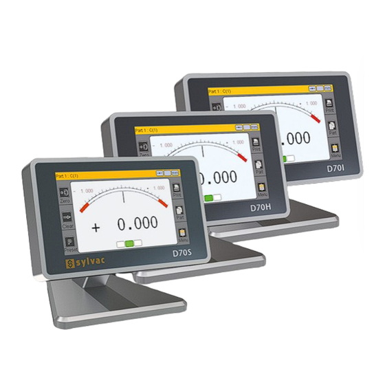
- Seite 1 Universal display unit Unité d’affichage universelle Universelle Anzeigeeinheit D70S/H/I User guide Manuel d’utilisation Bedienungsanleitung Software version V1.04 OS V1.00...
-
Seite 3: Inhaltsverzeichnis
Table of contents Introduction Versions Features Main technical features Dimensions and installation Connectivity D70S and D70I D70H Communication ports Connector pins Mini-USB connector Graphical interface The two main parts General details Configuration window Virtual keyboard Configuring the device and the measurements... -
Seite 4: Introduction
The D70 has a large number of customisable functions, making it suitable for a vast range of testing applications. The D70 display can be connected to a PC using its RS-232 and USB ports. A multifunctional pedal can also be connected to the device. Versions D70S D70H D70I Connections for Syl-... -
Seite 5: Dimensions And Installation
The D70 has four M5-thread holes, meaning that it can be affixed to a worktop, or the base can be removed in order to place it anywhere. Note: The four anti-slip pads need to be removed before the D70 can be affixed to a worktop. Connectivity D70S and D70I On/off button (hold for 2 s to switch off) -
Seite 6: D70H
D70H D70H On/off button (hold for 2 s to switch off) RS-232 connector for PC communication Connector for pedal Mini-USB connector for power supply and transferring the meas- 2 ports for Hein- urement to a PC dehain sensors Communication ports The D70 has an RS-232 port, which means that it can be connected to a machine or external system. -
Seite 7: Graphical Interface
Windows message confirming that the D70 has been correctly detected and installed: Graphical interface The graphical interface of your D70 has been designed for easy use. This chapter gives an over- view of the various screens and commands available. The two main parts The graphical interface of your D70 is made up of two main parts: •... -
Seite 8: General Details
General details The following information is visible at the top of the screen: Name of the active piece and calculation formula: Static or dynamic (max, Unit: mm, µm or min, etc.) mode inch Here, it is piece 1, sensor 1 Configuration window You can open configuration windows by tapping the icons in the icon panel. -
Seite 9: Virtual Keyboard
Virtual keyboard Delete Exit without saving the changes Save and exit Configuring the device and the measurements This chapter sets out the various windows that can be launched from the icon panel. As a re- minder, the icon panel can be launched by tapping the appropriate button on the measurement screen. -
Seite 10: Definitions
Definition Tapping the « definition » icon launches the following window. In this window, you can define the precision, unit, formula, tolerance, and benchmark of each of the two available configurations for the piece. This window has two areas allowing you to configure two pieces, and three screens that you can access using the scroll bar on the right: Choose piece 1 or 2 Move to... -
Seite 11: Display
Area 2 You can apply or remove the test limits from this screen, and define them if required. The test limits are alarms that will alert the user if a tolerance limit is reached (marked in yellow on the bar charts displayed on the measurement screen). This part is hidden if the option is set to «No»... -
Seite 12: Configuration
Configuration Tapping the « configuration » icon launches the following window. This window can be used to configure the communication settings for your D70. Select means of communication: RS-232 or USB Select language. Other languages may be added on request. Pedal function: •... -
Seite 13: Measurement
Choosing «yes» means that a password will be required to access the icon panel. Set password. The default is 0000 Allows the user to hide the buttons from the measurement screen. We rec- ommend that you only have the buttons that you need displayed on the meas- urement screen... -
Seite 14: Functions Of The Sidebar Buttons
Functions of the sidebar buttons Absolute or relative mode (allows you to create a zero point where required). If relative mode is selected, this button turns red. In order to return to absolute mode, tap the «Preset» button. Transfers the measurement (RS- 232 or USB) Manually changes... -
Seite 15: Temporary Dynamic Measurement Mode
You can switch between the two modes by tapping the display areas within the red dots below: Temporary dynamic measurement mode As explained in section 5.1, the value is defined as «static» or «dynamic» (min, max, etc.) If a value is set as static, it is still possible to temporarily switch to dynamic mode directly from the measurement screen. -
Seite 16: Tolerance-Free Mode
Tolerance-free mode This mode is very well suited to Heidenhain type incremental sensors (for example Heidenhain MT101). The tolerance-free mode allows only the numerical value to be displayed, without coloured tole- rance indications. In addition, it is possible to change the preset value (calibration) directly from the measurement screen. -
Seite 17: Communication Protocol
Communication protocol The D70 uses the ASCII communications protocol in order to run and configure its functions. Commands General details All commands must terminate with a «CR» character (ASCII code 13). The commands can be send in group by separing them with a character «;» (max 500 characters). The display is refresh after the reception of the character «CR». -
Seite 18: "Display" Window
Direction nDIR? nDIR=x x=0 (none) x=1 (internal) x=2 (external) Tolerance nUT? nUT=seee.ddddd Nominal nNM? nNM= seee.ddddd Lwr tolerance nLT? nLT?= seee.ddddd Standard nMT? nMT?= seee.ddddd Activate ctrl limits nLIMIT? nLIMIT=x x=0 (inactive) x=1 (active) Upper ctrl limit nUCL? nUCL= seee.ddddd Lower ctrl limit nLCL? nLCL= seee.ddddd... - Seite 19 «Configuration» window Item Read Write Comment command command Transfer PRINT=? PRINT=x x=0 (USB) x=1 (RS232) Language LANG? LANG=x x=0 (French) x=1 (English) x=2 (German) x=3 (Spanish) x=4 (Italian) x=5 (Hungarian) x=6 (Czech) x=7 (Swedish) x=8 (Portuguese) Pedal FOOT? FOOT=x x=0 (Print) x=1 (Preset) -->...
-
Seite 20: Display Calibration / Pairing With A Probe
This function should therefore be used with care. For this, follow the procedure below: 1. Switch off the D70 2. Switch on the D70 3. When the start screen appers, press Sylvac Logo 4. A desktop with five icons appears, press «Calibration». 5. The following screen appears... -
Seite 21: Linearisation / Correction Table
This allows a significant improvement in the performance of the related probes. For this, follow the procedure below: 1. Switch off the D70 2. Switch on the D70 3. When the start screen appers, press Sylvac Logo 4. A desktop with five icons appears, press «Calibration». 5. The following screen appears To activate the linearisation function, choose «Enabled»... -
Seite 22: Firmware Update
The D70 internal software can be updated. Updating requires an RS232 cable (ref. 926.5606 for D70S and ref 804.2201 for D70H/I) . It is possible to use an RS232/USB converter if your PC is not equipped with a serial port. -
Seite 23: Restoring Factory Settings
7 . Tap the «Home» icon to return to the meas- urement screen Applications Sylvac capacitive probes connected to a D70S Sylvac inductive probes connected to a D70i Heidenhain probes connected to a D70H Can be used to measure thickness, flatness, diameter, length, boring, recesses or positioning. -
Seite 25: French / Français / Französich
Table des matières English / Anglais / English Introduction Versions Caractéristiques Caractéristiques techniques principales Dimensions et installation Connectique D70S et D70I D70H Ports de communication Bornage du connecteur Connecteur mini-USB Interface graphique Les deux parties principales Généralités Fenêtre de configuration Clavier virtuel Configuration de l’appareil et de la mesure... -
Seite 26: Introduction
D70H D70I Connexions pour Connexions pour Connexions pour palpeurs capacitifs palpeurs Heidenhain palpeurs inductifs Sylvac ou compatibles Sylvac ou compatibles Caractéristiques Caractéristiques techniques principales • Ecran tactile couleur 4,3» résolution 480x272 • Mesures statiques ou dynamiques (Min, Max, Moyenne….) •... -
Seite 27: Dimensions Et Installation
Remarque : Pour fixer la D70 sur un plan de travail, il faut au préalable retirer les 4 pieds anti-dérapants. Connectique D70S et D70I Bouton marche/ arrêt (appuyer 2s. pour éteindre) -
Seite 28: D70H
D70H Bouton marche/ arrêt (appuyer 2s. pour éteindre) Connecteur RS232 pour communication PC Connecteur pour pédale Connecteur mini-usb pour alimentation et transfert de la mesure 2 entrées pour vers un PC capteurs Heindehain Ports de communication La D70 est équipé d’un port RS232. Il permet le raccordement de l’appareil à un automate ou à un système extérieur. -
Seite 29: Interface Graphique
Message apparaissant sous Windows pour confirmer que votre D70 a bien été détectée et installée : Interface graphique L ’interface graphique de votre D70 a été conçue pour être simple d’emploi. Ce chapitre donne un aperçu des différents écrans et commandes disponibles. Les deux parties principales L ’interface graphique de votre D70 se compose de 2 parties principales : •... -
Seite 30: Généralités
Généralités Les informations suivantes sont visibles sur la partie supérieure de l’écran : Nom de la pièce active et de la formule de calcul : Mode statique ou dyna- Unité : mm, µm, mique (Max, Min, etc..) ou inch Ici Pièce 1, palpeur 1 Fenêtre de configuration Des fenêtres de configuration s’ouvrent après avoir appuyé... -
Seite 31: Clavier Virtuel
Clavier virtuel Effacer Sortie sans prendre en compte la modification Sortie en validant Configuration de l’appareil et de la mesure Ce chapitre décrit les différentes fenêtres accessibles depuis le bureau d’icône. Pour rappel, si vous êtes sur l’écran de mesure, le bureau d’icône apparaît en cliquant sur le bouton de l’écran de mesure. -
Seite 32: Définition
Définition En cliquant sur l’icône « définition », la fenêtre ci-dessous apparaît. Elle permet de définir les résolutions, unité, formule, tolérances, la cote étalon, de chacune de 2 configuration de pièce disponible Cette fenêtre se divise en 2 zones pour la configuration des 2 références de pièces et en 3 écrans atteignables via la barre de défilement sur la droite : Choix de la pièce 1 ou 2 Aller à... -
Seite 33: Affichage
Zone 2 Cet écran permet d’afficher ou non les limites de contrôle, et de les définir le cas échéant. Les limites de contrôle sont des alarmes permettant d’alerter l’opérateur en cas de rapprochement d’une limite de tolérance (couleur jaune sur les bargraphes de l’écran de mesure) Cette partie est cachée si «... -
Seite 34: Configuration
Configuration En cliquant sur l’icône « configuration », la fenêtre ci-dessous apparaît. Cette fenêtre permet de configurer les paramètres de communication de votre D70. Choix du mode de communication : RS232 ou USB Choix de la langue. D’autres langues peuvent être ajou- tées sur demande. -
Seite 35: Mesure
Si oui, un mot de passe sera deman- dé pour accéder au bureau d’icônes. Choix du mot de passe. Par défaut : 0000 Permet de suppri- mer les boutons correspondant sur l’écran de mesure. Il est conseillé de ne laisser que les boutons utiles sur l’écran de mesure afin que l’inter-... -
Seite 36: Fonctions Des Boutons Latéraux
Fonctions des boutons latéraux Mode absolu ou relatif (permet de faire un « zéro » à une position voulue. Si le mode relatif est sélectionné, ce bouton devient rouge. Pour revenir en mode absolu, il faut appuyer sur le bouton « Preset » Transfert la mesure (RS232 ou USB) Change manuelle-... -
Seite 37: Mode De Mesure Dynamique Temporaire
Le passage entre chaque mode se fait en appuyant sur les zones d’affichage en pointillés rouges ci-dessous : Mode de mesure dynamique temporaire Comme expliqué dans le chapitre 5.1, la cote est définie en tant que « statique » ou « dynamique (Min, Max…). -
Seite 38: Mode Sans Tolérances
Mode sans tolérance Ce mode est très adapté avec des capteurs incrémentaux type Heidenhain (par exemple Heiden- hain MT101). Le mode sans tolérance permet d’afficher uniquement la valeur numérique sans indication colo- rée de tolérances. Il est de plus possible de changer la valeur de preset (étalonnage) directement depuis l’écran de mesure : Appuyer sur la valeur tel que représenté... -
Seite 39: Protocole De Communication
Protocole de communication Le D70 dispose d’un protocole de communication ASCII permettant de piloter et configurer l’en- semble des fonctions. Commandes Généralités Toutes les commandes doivent être terminée par un caractère « CR » (Code ascii 13). Les commandes peuvent être envoyées groupées en les séparants par un caractère «;» (max 500 caractères). - Seite 40 Sens nDIR? nDIR=x x=0 (sans) x=1 (interne) x=2 (externe) Tolérance nUT? nUT=seee.ddddd Nominal nNM? nNM= seee.ddddd Tolerance inf nLT? nLT?= seee.ddddd Etalon nMT? nMT?= seee.ddddd Activer limites de ctrl nLIMIT? nLIMIT=x x=0 (inactive) x=1 (active) Limite crtl sup nUCL? nUCL= seee.ddddd Limite ctrl inf nLCL? nLCL= seee.ddddd...
- Seite 41 Fenêtre «Configuration» Rubrique Commande Commande Commentaire en lecture en écriture Transfert PRINT=? PRINT=x x=0 (USB) x=1 (RS232) Langue LANG? LANG=x x=0 (Français) x=1 (Anglais) x=2 (Allemand) x=3 (Espagnol) x=4 (Italien) x=5 (Hongrois) x=6 (Tchèque) x=7 (Suédois) x=8 (Portugais) Pédale FOOT? FOOT=x x=0 (Print) x=1 (Preset) -->...
-
Seite 42: Calibration De L'afficheur/Apparaige Avec Un Palpeur
Pour cela, suivez la procédure suivante : 1. Mettre la D70 hors tension 2. Allumer la D70 3. Lorsque l’écran de démarrage apparaît, appuyez sur le logo Sylvac 4. Un bureau avec 5 icônes apparaît, appuyez sur «Calibration» 5. L ’écran suivant apparait La position du palpeur s’affiche :... -
Seite 43: Linéarisation / Table De Correction
Pour cela, suivez la procédure suivante : 1. Mettre la D70 hors tension 2. Allumer la D70 3. Lorsque l’écran de démarrage apparaît, appuyez sur le logo Sylvac 4. Un bureau avec 5 icônes apparaît, appuyez sur «Linearity» 5. L ’écran suivant apparait Pour activer la fonction de linéarisation, choisis-... -
Seite 44: Mise À Jour Du Firmware
Le logiciel interne de la D70 peut-être mis à jour. La mise à jours requiert un câble RS232 (réf. 925. 5606 pour D70S et réf 804.2201 pour D70H/I). Il est possible d’utiliser un convertisseur RS232/USB si votre PC n’est pas équipé d’un port série. -
Seite 45: Restauration Des Paramètres Usine
7 . Appuyer sur l’icône « Home » pour revenir sur l’écran de mesure Applications Palpeurs capacitifs Sylvac connectés à une Palpeurs inductifs Sylvac connectés à une D70i Palpeurs Heidenhain connectés à une D70H D70S Possibilité de mesurer des épaisseurs, planéités, diamètres, largeurs, alésages, décroche-... - Seite 47 Inhalt English / Anglais / English French / Français / Französich Einführung Versionen Eigenschaften Technische Haupteigenschaften Abmessungen und Installation Anschlüsse D70S und D70I D70H Kommunikationsports Kontaktbelegung des Anschlusses Mini-USB-Anschluss Grafische Benutzeroberfläche Die zwei Hauptbereiche Allgemeines Konfigurationsfenster Virtuelle Tastatur Konfiguration des Geräts und der Messung...
-
Seite 48: Einführung
D70 einen festen Platz unter den Kontrollanwendungen. Das Anzeigegerät D70 kann über seine RS232-Verbindung oder über USB an einen PC angeschlossen werden. Zudem kann ein Multifunktionspedal angeschlossen werden Versionen D70S D70H D70I Anschlüsse für kapaziti- Anschlüsse für Heiden- Anschlüsse für indukti-... -
Seite 49: Abmessungen Und Installation
Entfernung des Gerätefußes für eine leichtere Anbringung ermöglichen. Hinweis: Um das D70 auf einer Arbeitsplatte zu montieren, müssen zunächst die vier rutschsi- cheren Füße entfernt werden. Anschlüsse D70S und D70I Start-/Stopp-Tas- te (zum Ausschal- ten 2 s gedrückt... -
Seite 50: D70H
D70H Start-/ Stopp-Taste RS232-Anschluss zum (zum Ausschal- Datenaustausch mit ten 2 s gedrückt einem PC halten) Anschluss für Pedal Mini-USB-Anschluss für Stromversorgung und Übertragung der 2 Eingänge für Messung auf einen PC Heindehain-Sen- soren Kommunikationsports Das D70 verfügt über eine RS232-Schnittstelle. Sie ermöglicht das Anschließen des Instru- ments an einen Automaten oder ein externes System. -
Seite 51: Grafische Benutzeroberfläche
Meldung in Windows als Bestätigung, dass Ihr D70 richtig erkannt und installiert wurde: Grafische Benutzeroberfläche Die grafische Benutzeroberfläche Ihres D70 wurde so gestaltet, dass sie leicht zu bedienen ist. Dieses Kapitel gibt einen Überblick über die verschiedenen Anzeigen und möglichen Be- fehle. -
Seite 52: Allgemeines
Allgemeines Die folgenden Informationen sind im oberen Bereich der Ansicht zu sehen: Bezeichnung des aktiven Teils und Statischer oder dyna- der Berechnungsformel: Einheit: mm, µm mischer Modus (Max, Hier Teil 1, Messtaster 1 oder Zoll Min etc.) Konfigurationsfenster Nach Antippen der Icons auf der Icon-Oberfläche öffnen sich Konfigurationsfenster. Beispiel eines Fensters, das sich im Vordergrund der Icon-Oberfläche öffnet Die Informationen werden dann auf verschiedene Arten erfasst, gesichert und gewertet, nach- dem sie bestätigt und das Fenster geschlossen wurde. -
Seite 53: Virtuelle Tastatur
Virtuelle Tastatur Löschen Schließen ohne Ände- rungen zu übernehmen Bestätigen und schlie- ßen Konfiguration des Geräts und der Messung Dieses Kapitel behandelt die verschiedenen Fenster, die von der Icon-Oberfläche aus aufgeru- fen werden können. Zur Erinnerung: Wenn Sie sich in der Messanzeige befinden, erscheint die Icon-Oberfläche, wenn Sie die Taste für die Messanzeige anklicken. -
Seite 54: Definition
Definition Beim Anklicken des Icons « Definition », öffnet sich das unten abgebildete Fenster. Hier können für zwei Teile jeweils Auflösung, Einheit, Formel, Toleranzen und das Kali- brierungsmaß als Einstellungen definiert werden Dieses Fenster teilt sich in 2 Bereiche für die Konfiguration der Referenzen für die beiden Teile und in 3 Ansichten, zwischen denen man über den Scroll-Balken rechts wechseln kann: Wahl von Teil 1 oder 2 Wechseln zu... -
Seite 55: Anzeige
Bereich 2 In dieser Ansicht können Grenzwerte angezeigt oder ausgeblendet und ggf. definiert werden. Die Grenzwerte dienen als Alarmsignale, um den Bediener im Fall einer Annäherung an einen Toleranzwert zu warnen (gelbe Balken in der Messanzeige) Dieser Bereich ist ausgeblendet, wenn „nein“... -
Seite 56: Konfiguration
Konfiguration Beim Anklicken des Icons « Konfiguration », öffnet sich das unten abgebildete Fenster. Hier können Sie die Parameter für den Datenaustausch Ihres D70 einstellen. Wahl des Daten- austauschmodus: RS232 oder USB Wahl der Sprache. Weitere Sprachen können auf An- frage hinzugefügt werden. -
Seite 57: Messung
Wenn Sie „Ja“ eingeben, wird ein Passwort für den Zugriff auf die Icon-Oberfläche abgefragt. Wählen Sie ein Passwort. Standardeinstel- lung: 0000 Hiermit können entsprechende Schaltflächen in der Messanzeige deaktiviert wer- den. Es empfiehlt sich, in der Messanzeige nur zweckdienliche Schaltflächen beizubehalten, damit die Be- nutzeroberfläche... -
Seite 58: Funktionen Der Seitlichen Schaltflächen
Funktionen der seitlichen Schaltflächen Absoluter oder relativer Modus (ermöglicht ein „Null“-Stellen an einer festgesetzten Position). Wurde der relative Modus gewählt, wird diese Schaltfläche rot. Um in den absoluten Modus zurückzukehren, tippt man die Schaltflä- che „Preset“ an Übertragung der Messung (RS232 oder USB) Manueller Wech- Einleiten einer... -
Seite 59: Vorübergehender Dynamischer Messmodus
Zwischen den Modi kann man durch Antippen der unten abgebildeten, rot gestrichelten Anzei- gebereiche wechseln: Vorübergehender dynamischer Messmodus Wie in Kapitel 5.1 erläutert, wird die Maßzahl als „statisch“ oder „dynamisch“ (Min, Max ...) festgelegt. Auch wenn eine Maßzahl als statisch deklariert ist, ist es möglich, über die Messanzeige vorü- bergehend in den dynamischen Modus auszuweichen. -
Seite 60: Modus Ohne Toleranz
Modus ohne Toleranz Dieser Modus ist besonders geeignet für Inkrementalsensoren des Typs Heidenhain (z. B. Heiden- hain MT101). Der Modus ohne Toleranz ermöglicht die Anzeige des digitalen Werts ohne farbige Anzeige der Toleranzen. Darüber hinaus kann der voreingestellte Wert (Kalibrierung) direkt am Messbildschirm geändert werden: Tippen Sie wie unten dargestellt auf den Wert, und geben Sie den neuen Wert über die Tastatur ein: Die seitlichen Funktionen... -
Seite 61: Kommunikationsprotokoll
Kommunikationsprotokoll Die D70 verfügt über ein ASCII-Kommunikationsprotokoll, mit dem alle Funktionen gesteuert und konfiguriert werden können. Befehle Algemeines Alle Befehle müssen auf das Zeichen „CR“ (ASCII-Code 13) enden. Die Befehle können gruppiert abgeschickt werden, wobei die einzelnen Befehle durch das Zeichen „;“... - Seite 62 Richtung nDIR? nDIR=x x=0 (ohne) x=1 (innen) x=2 (außen) Toleranz nUT? nUT=seee.ddddd Nominal nNM? nNM= seee.ddddd Untere Toleranz nLT? nLT?= seee.ddddd Richtmaß nMT? nMT?= seee.ddddd Kontrollwert-Grenzen nLIMIT? nLIMIT=x x=0 (inaktiv) aktivieren x=1 (aktiv) Oberer Kontrollwert nUCL? nUCL= seee.ddddd Unterer Kontrollwert nLCL? nLCL= seee.ddddd Referenz...
- Seite 63 Fenster «Konfiguration» Bezeichnung Lesebefehl Schreibbefehl Anmerkung Übertragung PRINT=? PRINT=x x=0 (USB) x=1 (RS232) Sprache LANG? LANG=x x=0 (Französisch) x=1 (Englisch) x=2 (Deutsch) x=3 (Spanisch) x=4 (Italienisch) x=5 (Ungarisch) x=6 (Tschechisch) x=7 (Schwedisch) x=8 (Portugiesisch) Pedal FOOT? FOOT=x x=0 (Drucken) x=1 (Voreinstellung) --> Kalibrierung x=2 (Null) x=3 (Skala) x=4 (Init dynamisch)
-
Seite 64: Anzeigenkalibrierung/Abstimmung Mit Einem Sensor
Folgen Sie hierfür nachstehendem Ablauf: 1. Stromzufuhr zum D70 unterbrechen 2. D70 anschalten 3. Wenn der Startbildschirm erscheint, tippen Sie das Sylvac-Logo an 4. Eine Oberfläche mit 5 Icons erscheint. 5. Es erscheint folgende Anzeige Die Position des Messtasters wird angezeigt: - Setzen Sie den Wert auf Null - Setzen Sie ein Endmaß... -
Seite 65: Linearisierung/Korrekturtabelle
Folgen Sie hierfür nachstehendem Ablauf: 1. Stromzufuhr zum D70 unterbrechen 2. D70 anschalten 3. Wenn der Startbildschirm erscheint, tippen Sie das Sylvac-Logo an 4. Eine Oberfläche mit 5 Icons erscheint. 5. Es erscheint folgende Anzeige Um die Funktion Linearisierung zu aktivieren, wählen Sie „Aktiviert“... -
Seite 66: Aktualisierung Der Firmware
Aktualisierung der Firmware Die interne Software der D70 kann aktualisiert werden. Für die Aktualisierung ist ein RS232-Kabel erforderlich (Ref. 925.5606 für D70S und Ref 804.2201 für D70H/I). Es kann auch ein RS232/USB-Adapter verwendet werden, wenn Ihr PC nicht mit einer seriellen Schnittstelle ausgestattet ist. -
Seite 67: Zurücksetzen Auf Werkseinstellung
NO (nein) 7 . Tippen Sie auf das Icon „Home“ , um zur Messanzeige zurückzukehren Anwendungen D70S mit Kapazitiven Sylvac Messtaster D70i mit Induktiven Sylvac Messtaster D70H mit Heidenhain Messtaster Möglichkeit der Messung von Dicken, Ebenheiten, Durchmessern, Breiten, Bohrungen, Ab-... - Seite 69 Swiss Federal Office of Metrology. CERTIFICAT DE CONFORMITE Sylvac certifie que cet instrument a été fabriqué et contrôlé selon ses normes de Qualité et en référence avec des étalons dont la traçabilité est reconnue par l’office fédéral suisse de métrologie.
- Seite 70 CALIBRATION CERTIFICATE Because we make our Sylvac instruments in batches, you may find that the date on your ca- libration certificate is not current. Please be assured that your instruments are certified at point of production and then held in stock in our wa-rehouse in accordance with our Qua- lity Management System ISO 9001.
- Seite 72 Changes without prior notice Sous réserve de toute modification Änderungen vorbehalten Firmware version : r1.04 - 14.03.2014 Edition : 2016.09 / V1.0 / Man_D70_SYL 681.124...