Inhaltsverzeichnis
Werbung
Verfügbare Sprachen
Verfügbare Sprachen
Quicklinks
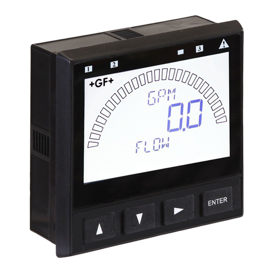
Signet 9900 Transmitter
*3-9900.091*
3-9900.091
Rev. 7
Panel Mount
Field Mount
•
English
•
Deutsch
•
Français
•
Español
•
Italiano
•
中文
07/18
English
Look for the Quick Start icon to
quickly set up your new 9900.
Description
The 9900 Transmitter, a member of Signet's line of SmartPro
instruments, provides a single-channel interface for all Flow,
pH/ORP, Conductivity/Resistivity, Salinity, Pressure, Temperature,
Level, Dissolved Oxygen, Turbidity, Batch and other applications.
The 9900 is available in either Panel or Field Mount, runs on
10.8 to 35.2 VDC power (24 VDC nominal), and can power
certain sensors on loop power (see NOTE on page 7).
The 9900 Transmitter, also allows third-party 4 to 20 mA signals
to be used as an input (optional Signet 8058 i-Go
Converter required, sold separately).
Compatibility
The 9900 is compatible with all
GF Signet products listed in the
column to the right.
• pH and ORP electrodes require the
Signet 2750/2751 DryLoc
Electronics (sold separately).
• Conductivity/Resistivity or Salinity
measurement requires either
the optional Direct Conductivity/
Resistivity Module (part number
3-9900.394) or the Signet 2850
Conductivity/Resistivity Sensor
Electronics (sold separately).
NOTE: If using the 2850, use ONLY
the one-channel Digital (S
3-2850-51/-61, or the 2-channel
model 3-2850-63 with only one
channel connected. Do not use
with both channels connected. The
4 to 20 mA models 3-2850-52 and
3-2850-62 are not compatible with
the 9900.
• Turbidity measurement using
Signet 4150 or Dissolved
• Oxygen measurement using
Signet 2610-31 requires Signet
8058 i-Go
(sold separately).
Start-Up Guide
Sensor
®
L) models
3
Signal Converter
®
English, Deutsch, 中文
Signal
®
Flow
515*/8510*, 525*, 2000,
2100, 2507, 2536*/8512*,
2537, 2540*, 2551, 2552
pH/ORP
2724-2726 with 2750*/2751
2734-2736 with 2750*/2751
2756-WTx–2757-WTx with
3719 and 2750*/2751
2764-2767 with 2750*/2751
2774-2777 with 2750*/2751
Conductivity/Resistivity,
Salinity
2819-2823 with 2850 or
Cond/Res Module
2839-2842 with 2850 or
Cond/Res Module
Level, Temperature,
Pressure
2250*, 2350*, 2450*
Turbidity
4150 requires 8058
Dissolved Oxygen
2610-41, 2610-51 direct
to 9900
* Can be run on Loop Power
(see NOTE on page 7)
®
Werbung
Inhaltsverzeichnis

Verwandte Anleitungen für GF SIGNET 9900


Inhaltszusammenfassung für GF SIGNET 9900
- Seite 1 ® Converter required, sold separately). Compatibility The 9900 is compatible with all Flow GF Signet products listed in the 515*/8510*, 525*, 2000, column to the right. 2100, 2507, 2536*/8512*, 2537, 2540*, 2551, 2552 • pH and ORP electrodes require the...
-
Seite 2: Warranty Information
All warranty and non-warranty repairs being returned must include a fully completed Service Form and goods must be returned to your local GF Sales offi ce or distributor. Product returned without a Service Form may not be warranty replaced or repaired. -
Seite 3: Module Installation
Plug-In Modules Optional modules and accessories are available for the 9900: a. Base Unit (required) b. Slot for optional H COMM or Modbus Module c. Slot for optional Cond/Res, Batch, or Output Module d. Slot for optional Relay Module (not available on fi eld mount) Each item is ordered separately. -
Seite 4: Installation
Installation System Start-up: Step 1 Prepare the transmitter installation location. If the back of the transmitter is diffi cult to access when installed, wire the removable terminal blocks fi rst, then install it completely. Next step: Wiring (Step 2). Do not mount in direct sunlight. gasket on front side of panel... - Seite 5 Wiring System Start-up: Step 2 Wire the transmitter for all connections with the power off. Keep any 4 to 20 mA and relay-actuated output devices that are connected to it offl ine at this time. Connect the sensors (pg. 7), power (pg. 13) and Open Collector and relay(s) (pg.
- Seite 6 Terminal Identifi cation The 9900 requires regulated 10.8 to 35.2 VDC (24 VDC nominal) from an external power supply (not supplied). Maximum current draw is: 200 mA = 9900 without Relay module 300 mA = 9900 with Relay module Terminals 1-2: DC Power Power •...
- Seite 7 Sensor Wiring Connect sensor wire plug here as shown in the following fi gures. Connect power and open collector wire plug here as shown on pages 13 and 14. NOTE: Loop Power can be used ONLY for the following sensors: 515/8510, 525, 2250, 2350, 2450, 2536/8512, 2540, 8058, and pH/ORP sensors with 2750;...
- Seite 8 Sensor Wiring NOTE: Loop Power can be used ONLY for the following sensors: 515/8510, 525, 2250, 2350, 2450, 2536/8512, 2540 and 8058; all other measurement sensors require DC power. Technical Notes: Wiring for: • See corresponding product manuals for 515/8510 2536/8512 2540 maximum cable length.
-
Seite 9: Sensor Wiring
Sensor Wiring Wiring for: Frequency 2551 Technical Notes: • When the blue jumper illustrated here is placed over both pins, 2551-XX-11 Blind Magmeter the 2551-XX-11 (Blind Magmeter) outputs an open Black collector frequency signal. When the White jumper is removed Shield (or placed over one pin for storage) the... - Seite 10 9900 set for a 1.0 cell constant. Wiring for: 9900 S L Inputs +GF+ Signet 8058 i-Go™ 8058-1 4-20 mA to S L Converter 4-20 mA input L Output Black 8058-1 Signet 8058 i-Go™...
- Seite 11 9900 LOOP– only via a 3-8058-1 or V– BLACK 24 VDC BLACK 3-8058 -2 i-Go Signal Power Supply +GF+ Signet 8058 i-Go™ 7310-XXXX Converter. 4-20 mA to S L Converter SHIELD (no connection) • Program the 9900 for...
- Seite 12 ALARM2 ALARM1 24 VDC – SHLD 4-20mA/ Technical Notes: +GF+ SIGNET RS-485 3 2 1 • When using the 8058-2, 6 5 4 connect the loop source to Loop1 Channel 1 input ONLY. SHLD...
-
Seite 13: Power Wiring
Power Wiring CAUTION! DO NOT connect your 9900 to AC power. The 9900 MUST be powered by 10.8 to 35.2 VDC ONLY. Stand-alone application, no current loop used ProcessPro 9900 (for reference only) Transmitter 9900 Terminals Terminals Black Power – System Pwr Loop - PWR + Power Supply... - Seite 14 Relay and Open Collector Wiring Open Collector Wiring NPN Style Wiring Pull-Up Resistor PWR + If PLC needs 0 logic input PWR – Power when relay is not energized, Loop + Supply Loop – set NORMAL to CLOSED in the RELAY menu when using OC –...
- Seite 15 Relay and Open Collector Wiring Relay Module Wiring The alarm is OFF during normal operation, and will go ON when ALARM! relay energizes according to 9900 Relay settings. AC or DC power The valve is ON during normal operation, and will go OFF when relay energizes according to 9900 Relay settings.
-
Seite 16: Operation
All possible segments shown in this illustration. The instrument's software controls which segments are shown at any particular time. Only the bar graph and GF logo are visible when the unit is turned off. Warning LED will be lit when No Sensor or Wrong Sensor is detected in Digital (S L) mode. -
Seite 17: System-Setup
System Setup System Setup: Menu Navigation This basic operating procedure repeats throughout the 9900 program: 1. Press ENTER for 3 seconds to ENTER enter EDIT menu. 2. Press ► to move to a specifi c Edit menu item. 3. Press ENTER key to select the item for editing. - Seite 18 System Setup System Setup: Step 3 Assign the appropriate sensor type for your system. All of the basic system setup functions are automated in the 9900 for almost all sensors and sensor electronics. This includes assigning the sensor connected to the 9900, and confi guring the display for the sensor.
-
Seite 19: Ordering Information
Ordering Information 9900 Transmitter Base Unit: Single Channel, Multi-Parameter, 4 to 20 mA, Open Collector, DC Power Mfr. Part No Code Description 3-9900-1P 159 001 695 9900 Base Unit, Panel Mount 3-9900-1 159 001 696 9900 Base Unit, Field Mount 3-9900-1BC 159 001 770 Batch Controller System Optional Modules... - Seite 20 9900 Transmitter Start-Up Guide...
- Seite 21 Signet 9900 Transmitter *3-9900.091* 3-9900.091 Rev. G 02/17 Deutsch Inbetriebnahmehandbuch Achten Sie auf das Schnellstart-Symbol, um den neuen 9900 schnell einzurichten. Beschreibung Der 9900 Transmitter ist Teil der Produktlinie von Signet SmartPro™ Geräten und bietet eine Einzelkanalschnittstelle für alle Durchfl uss-, pH/ORP-, Leit-/Widerstandsfähigkeits-, Salzkonzentrations-, Druck-,...
-
Seite 22: Garantieinformationen
Alle zurückgesandten Garantiereparaturen und Reparaturen außerhalb der Garantiedauer müssen ein vollständig ausgefülltes Serviceformular einschließen, und die Produkte müssen an Ihre örtliche GF Geschäftsstelle oder an Ihren Händler zurückgegeben werden. Produkte, die ohne ein Serviceformular zurückgesendet werden, werden möglicherweise nicht unter Garantiebedingungen ersetzt oder repariert. -
Seite 23: Plug-In-Module
Plug-in-Module Für den 9900 sind optionale Module und optionales Zubehör erhältlich: a. Basiseinheit (erforderlich) b. Steckplatz für optionales H-COMM-Modul oder Modbus Modul c. Steckplatz für optionales Leit-/Widerstandsfähigkeits-, Batch- oder Ausgangsmodul d. Steckplatz für optionales Relaismodul (bei Feldmontage nicht verfügbar) Jedes Element wird separat bestellt. Module können jederzeit im Feld ersetzt werden. - Seite 24 Installation Inbetriebnahme des Systems: Schritt 1 Installationsort des Transmitters vorbereiten. Falls die Rückseite des Transmitters bei der Installation nur schwer zugänglich ist, zuerst die Verdrahtung der entfernbaren Klemmenleisten vornehmen und dann die Installation abschließen. Nächster Schritt: Verdrahtung (Schritt 2). Dichtung vorne an Ohne direkte Sonneneinstrahlung montieren.
- Seite 25 Verdrahtung Inbetriebnahme des Systems: Schritt 2 Für alle Anschlüsse die Verdrahtung bei ausgeschaltetem Transmitter durchführen. Zu diesem Zeitpunkt müssen alle angeschlossenen 4- bis 20-mA- und relaisbetätigten Ausgangsgeräte offl ine sein. Die Sensoren (S. 27), den Strom (S. 33) und das/die Relais (S. 34). Nächster Schritt: System-Setup (Schritt 3).
- Seite 26 Anschlussidentifi zierung Der 9900 erfordert geregelte 10,8 bis 35,2 VDC (24 VDC nominal) von einer externen Stromversorgung (nicht im Lieferumfang enthalten). Die maximale Stromaufnahme beträgt: 200 mA = 9900 ohne Relaismodul 300 mA = 9900 mit Relaismodul Anschlüsse 1-2: Gleichstrom Strom •...
-
Seite 27: Sensorverdrahtung
Sensorverdrahtung Sensordrähte hier anschließen (siehe nachfolgende Abbildungen). Strom- und Open- Kollektor-Drähte hier anschließen (siehe S. 33 und 34). HINWEIS: Schleifenstrom kann NUR mit den folgenden Sensoren verwendet werden: 515/8510, 525, 2250, 2350, 2450, 2536/8512, 2540, 8058 und pH/ORP- Sensoren mit 2750; alle anderen Messsensoren erfordern Gleichstrom. Schleifenstromsysteme können nicht gleichzeitig ein H-COMM-Modul und pH-Sensoren in einem System betreiben. - Seite 28 Sensorverdrahtung HINWEIS: Schleifenstrom kann nicht zum Betrieb der Signet 2000, 2100, 2507, 2537, 2551 oder 2552 Durchfl usssensoren verwendet werden. Technische Hinweise: Verdrahtung für: • Siehe entsprechende Produkthandbücher für maximale Kabellänge. 515/8510 2536/8512 2540 • Die Kabelabschirmung durch Kabelspleiße FLOW hindurch erhalten.
- Seite 29 Sensorverdrahtung Verdrahtung für: 2551 Technische Hinweise: • Wenn der hier Frequenz gezeigte blaue Jumper über beide Stifte positioniert ist, gibt der 2551-XX-11 (Blinder elektromagnetischer Durchfl usssensor) * 2551-XX-11 ein Open-Kollektor- Blinder elektromagnetischer Frequenzsignal aus. Durchflusssensor Wenn der Jumper entfernt wird (oder zur Schwarz Aufbewahrung auf einen einzelnen Stift...
- Seite 30 Sondenzellkonstante und der 9900 auf eine Zellkonstante von 1,0 eingestellt werden. Verdrahtung für: 9900 S L-Eingänge +GF+ Signet 8058 i-Go™ 8058-1 4-20 mA to S L Converter 4-20 mA input L Output Technische Hinweise: • Die Kabellänge vom...
- Seite 31 3-8058-1 oder -2 i-Go LOOP– Signalwandler am V– 9900 angeschlossen 24-VDC- SCHWARZ SCHWARZ Stromversorgung werden. +GF+ Signet 8058 i-Go™ 7310-XXXX 4-20 mA to S L Converter ABSCHIRMUNG • Den 9900 für den (nicht angeschlossen) WEISS 4-20 mA input L Output 2610 DO-Sensor über...
- Seite 32 Nennwerte des Geräts gefährdet und es besteht ALARM2 ALARM1 24 VDC die Möglichkeit einer – SHLD Stromschlaggefahr. 4-20mA/ +GF+ SIGNET RS-485 3 2 1 • 4- bis 20-mA-Kabel nicht 6 5 4 im selben Installationsrohr Loop1 wie Stromkabel verlegen. SHLD ISL 1 Loop2 •...
- Seite 33 Stromverdrahtung VORSICHT! Den 9900 NICHT an Wechselstrom anschließen. Der 9900 DARF NUR mit 10.8-35.2 VDC betrieben werden. Eigenständige Anwendung, ohne Stromschleifennutzung ProcessPro 9900 (nur zur Referenz) 9900 Transmitteranschlüsse Anschlüsse Schwarz Spannungs- Spannungs- – Systemstromschleife – Spg.versorgung + versorgung versorgung – Spg.versorgung - Systemstromschleife + 12 bis 24 VDC...
-
Seite 34: Relais- Und Open-Kollektor-Verdrahtung
Relais- und Open-Kollektor-Verdrahtung Open-Kollektor-Verdrahtung NPN-Verdrahtung Pull-Up-Widerstand Wenn die SPS einen 0-Logikeingang Spg.versorgung + Spg.versorgung - erfordert, wenn das Relais nicht Spannungs- Stromschleife + erregt ist, NORMAL (Ruhekontakt) versorgung Stromschleife - auf CLOSED (Arbeitskontakt) im Masse Open- Open- Kollektor Kollektor Menü RELAY (Relais) einstellen, –... -
Seite 35: Passwortüberblick
Relais- und Open-Kollektor-Verdrahtung Relaismodulverdrahtung Der Alarm ist während des Normalbetriebs AUSGESCHALTET ALARM! und wird EINGESCHALTET, wenn das Relais gemäß den Relaiseinstellungen des 9900 Wechsel- oder erregt wird. Gleichstrom Das Ventil ist während des ALARM! Normalbetriebs EINGESCHALTET und wird AUSGESCHALTET, wenn das Relais gemäß den Relaiseinstellungen des 9900 erregt wird. -
Seite 36: Betrieb
Alle möglichen Segmente sind in dieser Abbildung gezeigt. Die Software des Geräts steuert, welche Segmente zu einem bestimmten Zeitpunkt angezeigt werden. Nur das Balkendiagramm und das GF-Logo sind sichtbar, wenn das Gerät ausgeschaltet ist. Die Warnanzeigen-LED leuchtet auf, wenn im digitalen (S L) Modus kein Sensor oder ein falscher Sensor erkannt wird. -
Seite 37: System-Setup
System-Setup Systemeinrichtung: Menünavigation Dieses grundlegende Betriebsverfahren wiederholt sich während des 9900 Programms: 1. Die ENTER-Taste 3 Sekunden ENTER lang drücken, um den Modus EDIT (Bearbeiten) aufzurufen. Bearbeitung 2. ► drücken, um zum gewünschten Menü zu navigieren. 3. Die ENTER-Taste drücken, um es auszuwählen. - Seite 38 System-Setup System-setup: Schritt 3 Den 9900 auf die installierten Sensoren anpassen Für fast alle Sensoren und Sensorelektronik sind die grundlegenden Systemeinrichtungsfunktionen beim 9900 automatisiert. Dazu zählen die Zuordnung des am 9900 angeschlossenen Sensors und die Konfi guration der Anzeige für den Sensor. ENTER Nach der Installation und Verdrahtung zum Abschnitt in diesem Handbuch gehen,...
- Seite 39 Bestellinformationen 9900 Basiseinheit - Einzelkanal, Multi-Parameter, 4 bis 20 mA, Open-Kollektor, Gleichstrom Hersteller- Teile- Code Beschreibung 3-9900-1P 159 001 695 9900 Transmitter, Schaltschrankinstallation 3-9900-1 159 001 696 9900 Transmitter, Feldinstallation Feldmontage 3-9900-1BC 159 001 770 9900-1BC Batch Controller Optionale Module 3-9900.393 159 001 698 Relaismodul - zwei Schwachstromkontaktrelais 3-9900.394...
- Seite 40 9900 Transmitter Inbetriebnahmehandbuch...
- Seite 41 变送器 Signet 9900 *3-9900.091* 3-9900.091 Rev. G 02/17 中文 调试向导 寻找快速启动图标以 快速设定新的9900 描述 9900变送器,作为Signet SmartPro™ 产品线成员,提供流 量,pH/ORP,电导率/电阻率,盐度,压力,温度,液位, 溶解氧, 用于批处理, 浊度和其他应用的单通道接口。 9900有盘面安装和现场安装版本。 两个版本均10.8 - 35.2 VDC供电 (额定值24 VDC), 并且可以在回路中给相应的传感器供电 (见注47页) 提供可用于接受第三方的4-20 mA 信号作为输入的通用工具 (需要可选的 Signet 8058 i-Go ® 信号转换器,需单独购买)。 盘面安装 兼容性...
- Seite 42 质保信息 请咨询当地GF销售公司以获得当前质保条款 所有质保或非质保维修必须填写服务表格,实物寄送到GF办公室或经销商。 未填写服务表格的返回产品不能质保更换或维修 Signet 货架寿命有限的产品(如 pH, ORP, 余氯传感器,标定溶液; 如, pH 缓冲液, 浊度标准也或其他溶液) 从包装中取出也提供质保。但不对任何过程或应用中导致 的损坏质保 (例如. 高温, 化学腐蚀,变干)或错误操作(如. 玻璃损坏, 膜片损坏, 冻结和/或极端温度). 产品登记 感谢您购买GF的Signet测量产品 如需要注册产品,可如下在线操作: • 访问 www.gfsignet.com 点击 Service and Support 点击 Product Registration Form • 如果是pdf说明书(数字版本),点击这里 安全信息 • 请按本说明小心操作,避免人身伤害。...
- Seite 43 可插拔模块 9900的可选模块和附件: a. 主单元(必须) b. H COMM模块和Modbus模块使用的是同一个的插槽 c. 可选电导/电阻,批处理,或输出模块的插槽 d. 插槽用于可选的继电器模块. (不能用于现场安装版本) 各模块需要单独订货 各模块可随时更换 更多细节参考订货信息和9900说明书 9900一代 9900 模块 注意: 4-20mA电流输出模块,电导模块, H COMM 模块* 批处理模块,安装于9900主单元的 同一位置. Modbus H COMM模块和Modbus模块在9900上 继电器 模块 使用相同的安装位置,因此每个9900 电导模块 变送器只能安装其中的一个模块。 批处理模块 注意: 在OPTIONS 菜单中区分9900变送 4-20mA输出模块* 器的版本号 * 可以用回路电源供电 模块安装...
- Seite 44 安装 系统启动:第一步 确定变送器安装位置。如安装后无法接触背面, 先进行可移动的端子排接线, 再整天安装。 下一步:接线 避免阳光直射 盘面安装 所需工具 细锉刀 • 可确保1 mm (0.02 in)盘面切割公差的¼ DIN 钻枪或竖 锯 • ¼ DIN 钻枪是推荐的的的仪表盘面开孔工具,整洁,精 确,快速且简单。 • 竖锯或其他开孔工具是次优选择。使用锉刀取出毛刺并 抛光 1. 变送器盘面安装的开孔的需要一个 ¼ DIN的钻枪。 手动盘面开孔,可使用提供的可粘贴安装指引标 签。 如安装多个变送器,变送器的各个边的最小间 隙25 mm (1 in). 2. 将变送器安装如孔前需先给变送器装上垫圈。 3. 在变送器后部套入安装支架,直到卡住变送器边缘 的卡槽并锁死。...
- Seite 45 接线 系统启动: 步骤2 变送器所有的接线需在断开电源时完成。 同时保持4-20mA和继电器回路断开。 传感器接线(见47页),电源接线(见53页)和 继电器接线(见54页)。 下一步:菜单设定 接线提示: 所需工具 ●十字螺丝刀 • 将传感器,直流系统电源,或4-20mA电缆与交流电分开走 ●平头螺丝刀 线槽。 电气噪声会干扰传感器信号 ●剥线钳 • 使用金属线槽走传感器电缆可以阻止电气噪声和机械损伤 • 密封穿线口以避免潮气 对于现场安装, • 一个端子只能接一根线 参考现场安装 • 端子排如接两根线需要先端子排外拧合或使用合适的线鼻 外壳内置的接 子,直径不超过 2 mm (0.08 in)。 线图 所有9900的接线都通过可移动的端子排完成。 要点归纳: • 端子排需使用12-24 AWG 电缆(电导率/电阻率模块为 16-28 AWG 电缆)。...
- Seite 46 端子排编号 9900供电等级 10.8 - 35.2 VDC (24 VDC 额定) 外部供电 (用户自备) 最大上拉电流: 200 mA = 9900 不带继电器模块 300 mA = 9900 带继电器模块 端子 1-2: 系统电源 电源 给变送器供电 • 为传感器,继电器和LCD背光提供10.8-35.2 VDC 电源。 PWR + PWR – 端子 3-4: 回路电源 (也可用作系统电源) Loop + •...
- Seite 47 传感器接线 按图接传感器线 参考第53和54页 接电源和集电极 开路输出线 注意: 回路电源只能用于以下传感器:515/8510, 525, 2250, 2350, 2450, 2536/8512, 2540, 和 8058 和带 2750的 pH/ORP; 其他的传感器需要直流电源。 回路电源不能同时给同一测量系统的 H COMM 模块和pH传感器供电。 如果同时使用 H COMM 模块和pH传感器,需要 DC 电源供电。 9900一代 数字信号 传感器类型 频率输出 回路电流供电 L) 输出 515 / 8510 2000 2100 2250 2350...
- Seite 48 传感器接线 注意:回路电源不能用于2000, 2100, 2507, 2537, 2551 或 2552流量传感器 如下传感器接线: 技术提示: 频率 • 最大电缆长度见 相关产品手册 • 延长电缆时需保 持屏蔽线 • 远离交流电缆布线 • 515/8510 和 525 的安装,如有EMI 电磁干扰需将银 色屏蔽线接地。 FLOW 接线 技术提示: • 2537 需要 2537-5 16 - 22 AWG电缆 9900 • 电缆直径 7 mm - 10 mm (0.275 in.
- Seite 49 传感器接线 接线 技术提示: • 蓝色跳线如图放 置在两个针脚, 2551-XX-11 (无 显示电磁流量计) 输出集电极开路 信号。当不放置 (或只放置在一个 针脚) 2551-XX- 11 输出数字信号 L) (推荐)。 如有EMI干扰 见(2551 & 2552) 频率输出技术说明右侧 技术提示 (频率输出): • 频率输出不论流向 只显示为正向。 2551和2552传感器输入接线 • 9900 向 2551 提 • 频率和数字信号 (S L) 二选一 供 5 VDC。 •...
- Seite 50 传感器接线 接线 2250 2350 2450 技术提示: • 使用最大为305 m 9900 (1000 ft) 的3芯屏 蔽线作为传感器 延长线 • 延长电缆时需保 2551* 2750/2751 2850 持屏蔽线 • 远离交流电缆布线 • 如有EMI电磁干扰 需将银色屏蔽线 接地 • 为了正确配合 * 2551-XX-21, -41 9900 使用, 2850 需要设定客户常 数或确切的电极 常数, 且 9900 应 设定常数为1.0。...
- Seite 51 9900 • 3-2610-31 溶解氧 PWR+ PWR– 传感器只能通过 LOOP+ 3-8058-1 或 -2 i-Go LOOP– 信号转换器连接到 V– 9900. +GF+ Signet 8058 i-Go™ 4-20 mA to S L Converter • 通过9900上 4-20 mA input L Output 4-20mA 传感器设 8058-1 定菜单对连接到 9900的2610溶解氧 DO Sensor 传感器进行设定.
- Seite 52 • 请勿将4~20mA电缆 与电源电缆放置在同 一线槽。 EMCF1 RLY2 RLY1 技术说明 • 如使用8058-2,仅使用 ALARM2 ALARM1 24 VDC 通道一与 9900连接 – SHLD 4-20mA/ +GF+ SIGNET RS-485 3 2 1 6 5 4 Loop1 SHLD ISL 1 Loop2 9900 DATA 7 8 9 9900 变送器调试向导...
- Seite 53 电源接线 注意! 不可将9900接到交流电源 9900供电为10.8 to 35.2 VDC 无电流输出回路的应用 Stand-alone application, no current loop used System Pwr Loop - – PWR + PWR – – System Pwr Loop + Loop + AUX Power - Loop – AUX Power + Connection to a PLC/Recorder, separate supply PWR + –...
- Seite 54 继电器和集电极开路接线 集电极开路接线 NPN 型接线 PWR + 如果PLC需要继电器失电 PWR – Loop + 状态下为逻辑0, Loop – 在RELAY菜单Open OC – Collector(R1)的NPN类型 Input 设定NORMAL为CLOSED PNP 型接线 PWR + PWR – Loop + Input Loop – OC – +5V to +24V NORMAL设定为OPEN PWR + PWR – Loop + Loop –...
- Seite 55 继电器和集电极开路接线 继电器模块接线 通过9900 中Relay 菜单的设定, 正常操作时报警关闭, 继电器得电时打开. 通过9900 中Relay 菜单的设定, 正常操作时阀门打开, 继电器得电时关闭 NO = 常开(得电关闭) NC = 常闭(得电打开) 密码概览 在开始编辑时需要输入密码。如正确输入,随后的编辑不再需要密码。 然而,当退出菜单系统时,再次进入编辑模式仍会需要密码 密码的选择 (STD 或 CODE) 在 OPTION 模式下进行。 ●STD STANDARD (STD) 密码为 ▲▲▲▼ 按需输入。此密码可防止对 9900 的无 意操作。适合于若干人需要同时能进行设定的改变的情况 ●CODE CODE 默认值为 0000, 0000-9999 范围可任意修改。 使用个人密码可以实现最大程度的安全性。此密码在...
- Seite 56 操作 ENTER 上图列出了所有可能的符号。变送器软件控制这些符号在特定时间出现。 只有棒状图和+GF+图标在变送器断电时仍可见。 当在S3L数字模式下检测到没有传感器或传感器错误,LED警告指示灯将会点亮 上,下方向键 滚动菜单选项或修改设定值 两键同按退出菜单或不保存退出 右方向键选择需要编辑的项 ENTER 键 进入菜单 ENTER 保存设置 9900 变送器调试向导...
- Seite 57 菜单系统 系统设定: 菜单导航 9900变送器基本操作步骤: 1. 按 ENTER 键3秒进入菜单 2. 按 ► 移动到所需菜单然后按 ENTER 进行 选择(可能会需要密码) 3. 按 ▲ 或 ▼ 选择所需菜单进行编辑 4. 按 ► 编辑数值/选择菜单 5. 按 ENTER键保存新数值/选择。 6. 按 ▲ 或 ▼ 选择其他菜单,根据需要 重复按3-5次 7. 按 ▲ 或 ▼ 选择不同菜单,根据需要 重复按2-5次。...
- Seite 58 菜单系统 菜单调试:步骤3 分配适当的传感器类型为您的系统。 9900中已内置很多的传感器和电子变 送组件的基本系统设定功能。 ENTER 包括区分连到 9900的传感器类型, 组态传感器显示。在安装和接线完成后, 进入本说明书传感器参数的章节。 9900初次上电会尝试确定所连接的传 感器类型 (将显示 LOOKING FOR)。 如没有传感器与9900相连, 会显示 "TYPE" 和 "FLOW"。 如果9900未能正确判别出当前传感器类型, 使用▲和▼键来选择你的传感器类型。 按ENTER键保存被选项 ENTER 提示:只有当远程批处理模块安装时, 9900显示批处理类型 请参阅9900操作说明 (3-9900.090) 的校准您的个性化的传 感器类型和单位调整继电器/集电极开路设置的详细说明。 9900 变送器调试向导...
- Seite 59 订货信息 9900 主单元 - 单通道l, 多参数, 4 - 20 mA, 集电极开路输出, 直流电源 产品编号 订货代码 描述 3-9900-1P 159 001 695 9900 主单元, 盘面安装 3-9900-1 159 001 696 9900 主单元, 现场安装 3-9900-1BC 159 001 770 批处理控制系统 可选模块 3-9900.393 159 001 698 继电器模块 - 2路干接点继电器 3-9900.394 159 001 699 电导/ 电阻率模块...
- Seite 60 中国公司联系方式: • 上海乔治费歇尔管路系统有限公司 • 深圳分公司 • 地址: 上海浦东康桥东路218号 • 地址: 深圳罗湖区人民南路深圳 • 邮编: 201319 发展中心大厦1401 • 电话: 021-3899 3899 • 传真: 021-3899 3888 • 邮编: 518001 北京分公司 • 电话: 0755-8228 0172/73 • 地址: 北京市朝阳区朝外大街22号泛利大厦1205A • 传真: 0755-2519 2297 • 邮编: 100020 西安分公司...