
Verwandte Anleitungen für Optika B-500 MET


Inhaltszusammenfassung für Optika B-500 MET
- Seite 1 Ver. 1.0.0 B-500 MET OPERATION MANUAL GUIDA UTENTE MANUAL DE INSTRUCCIONES BEDIENUNGSANLEITUNG OPTIKA MICROSCOPES - ITALY www.optikamicroscopes.com - info@optikamicroscopes.com...
-
Seite 2: Inhaltsverzeichnis
INDEX SAFETY GUIDELINES page 3 1.0 DESCRIPTION page 4 2.0 INTRODUCTION page 6 3.0 UNPACKING AND ASSEMBLY page 6 4.0 USING THE MICROSCOPE page 8 5.0 MAINTENANCE page 11 6.0 ELECTRICAL SPECIFICATIONS page 11 7.0 RECOVERY AND RECYCLING page 12 Page 2... -
Seite 3: Safety Guidelines
Optika reminds you that this manual contains important information on safety and maintenance, and that it must therefore be made accessible to the instrument users. Optika declines any responsibility deriving from instrument uses that do not comply with this ma- nual. -
Seite 4: Description
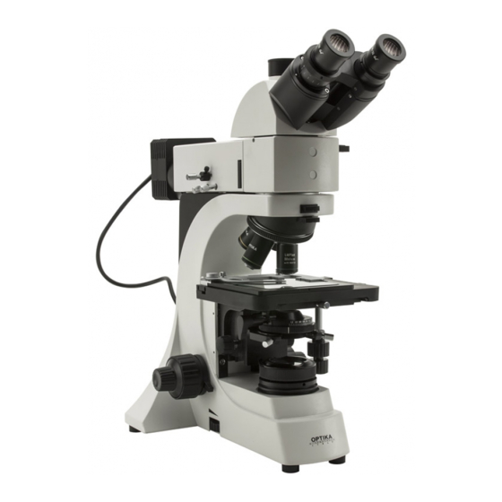
1.0 DESCRIPTION Dioptric adjustment ring Eyepiece Photo Port selector lever Nosepiece Objectives Stage Iris diaphragm Field diaphragm Fine focusing knob Coarse focusing knob Tension adjustment knob Brightfield brightness adjustment knob (epil- lumination knob on the other side) Page 4... - Seite 5 1.0 DESCRIPTION Metallographic features White LED housing Darkfield lever Diaphragm centring screws Field diaphragm Aperture diaphragm Analyzer filter (rotating) Diaphragm centering Polarizer filter screws Page 5...
-
Seite 6: Introduction
Optika reminds you that this manual contains important information on safety and maintenance, and that it must therefore be made accessible to the instrument users. Optika declines any responsibility deriving from instrument uses that do not comply with this manu- 3.0 UNPACKING AND ASSEMBLY The microscope is housed in a moulded Styrofoam container. - Seite 7 3.0 UNPACKING AND ASSEMBLY Place the observation head into the top of the attachment and tighten the lock-screw. Insert the eyepieces into the eye tubes. Insert polarizer and analyzer filters into their slots in the metallographic attachment. Connect the power cable of the epillumination to the appropriate connector on the rear. Connect the mains plug into the socket at the base Make sure, before you turn the illumination on, that the voltage selector is set to the mains voltage for your region.
-
Seite 8: Using The Microscope
4.0 USING THE MICROSCOPE Adjust the observation head Loosen the lock-screw, turn the observation head to a comfortable position for observation, and then lock the lock-screw. Place the specimen on the stage Put the specimen on the mechanical stage (transparent glass plate). Ensure that the speci- men is centred over the stage opening by adjusting the coaxial knobs of the stage. -
Seite 9: Adjust Interpupillary Distance
4.0 USING THE MICROSCOPE 4.10 Video capturing (optional) B-500MET be connected to cameras via a photo/video adaptor, for photo and video captur- ing. Before taking a picture or filming video, if necessary, obscure with a dark cloth both the camera viewfinder and the eyepieces and pull out the light path selector lever. Please refer to the adaptor and camera manuals for further details. -
Seite 10: Set The Numerical Aperture
4.0 USING THE MICROSCOPE At the bottom of the lever, on both sides of the microscopes, there is a couple of screws that can centre the field diaphragm. 4.15 Set the numerical aperture Adjust the aperture of the iris diaphragm to set the numerical aperture of the epilluminator, thus controlling image contrast and resolution. -
Seite 11: Maintenance
Mishandle or impose unnecessary force on the microscope. Clean the unit with volatile solvents or abrasive cleaners. Attempt to service the microscope yourself. If you need to send the microscope to Optika for maintenance, please use the original packa- ging. 6.0 ELECTRICAL SPECIFICATIONS... -
Seite 12: Recovery And Recycling
7.0 RECOVERY AND RECYCLING Art.13 Dlsg 25 july 2005 N°151. “According to directives 2002/95/EC, 2002/96/EC and 2003/108/EC relating to the reduction in the use of hazardous substances in electrical and electronic equipment and waste disposal.” The basket symbol on equipment or on its box indicates that the product at the end of its useful life should be collected separately from other waste. - Seite 14 INDICE INDICAZIONI PER LA SICUREZZA pag 15 1.0 DESCRIZIONE pag. 16 2.0 INTRODUZIONE pag. 18 3.0 DISIMBALLAGGIO E INSTALLAZIONE DEL MICROSCOPIO pag. 18 4.0 UTILIZZO DEL MICROSCOPIO pag. 20 5.0 MANUTENZIONE DEL MICROSCOPIO pag. 23 6.0 SPECIFICHE ELETTRICHE pag. 23 7.0 MISURE ECOLOGICHE pag.
-
Seite 15: Indicazioni Per La Sicurezza
Optika ricorda che il presente manuale contiene informazioni importanti per un uso sicuro e una corretta manutenzione dello strumento. Esso deve quindi essere accessibile a chiunque lo utilizzi. - Seite 16 1.0 DESCRIZIONE Anello di compensazione Oculare diottrica Levetta di selezione Uscita Foto-Video Revolver Obiettivi Tavolo Diaframma di apertura Diaframma di campo Manopola focus micrometrico Manopola focus macrometrico Ghiera di regolazio- ne tensione Manopola di regolazione intensità campo chiaro (manopola per l’epilluminazione sull’altro lato) Pagina 16...
- Seite 17 1.0 DESCRIZIONE Caratteristiche metallografiche Alloggiamento LED bianco Levetta per campo scuro Viti di centraggio diaframmi Diaframma di campo Diaframma di apertura Filtro analizzatore Viti di centraggio (ruotabile) Filtro polarizzatore diaframmi Pagina 17...
- Seite 18 Optika ricorda che il presente manuale contiene informazioni importanti per un uso sicuro e una corretta manutenzione dello strumento. Esso deve quindi essere accessibile a chiunque lo utilizzi.
- Seite 19 3.0 DISIMBALLAGGIO E INSTALLAZIONE DEL MICROSCOPIO Posizionare la testa ottica sulla sommità dell’attacco metallografico e stringere la relativa vite di fissaggio (sul lato sinistro). Inserire gli oculari nei tubi della testa ottica. Inserire i filtri polarizzatore e analizzatore nei rispettivi slot nell’attacco metallografico (vedi immagine nella sezione Descrizione).
- Seite 20 4.0 UTILIZZO DEL MICROSCOPIO Regolazione della testa ottica Allentare la vite di serraggio, ruotare la testata fino a trovare una posizione comoda per l’osservazione e quindi avvitarla nuovamente. Posizionamento del campione sul tavolino Posizionare il campione sul tavolino meccanico (sulla lastra di vetro di supporto). Assicurarsi che il campione sia centrato regolando la posizione con le manopole coassiali.
-
Seite 21: Utilizzo Del Microscopio
4.0 UTILIZZO DEL MICROSCOPIO 4.10 Acquisizione video e foto (opzionale) La serie B-500MET è collegabile a una telecamera con un adattatore per acquisire foto e video. Prima di procedere all’acquisizione di immagini video/foto, se necessario, si consiglia di oscurare con un panno scuro sia il mirino della macchina fotografica/videocamera che gli oculari e di staccare la levetta di selezione del percorso ottico. -
Seite 22: Analisi In Polarizzazione
4.0 UTILIZZO DEL MICROSCOPIO Sotto la levetta, su entrambi i lati dell’attacco, c’è una coppia di viti tramite le quali è possibile centrare il diaframma. 4.15 Impostare l’apertura numerica Regolare l’apertura del diaframma ad iride per impostare l’apertura numerica dell’epillumi- natore, per variare quindi il contrasto di immagine e la risoluzione. -
Seite 23: Specifiche Elettriche
Non pulire lo strumento con solventi volatili o agenti pulenti abrasivi. Non cercare di provvedere da soli alla manutenzione. Si prega di utilizzare l’imballaggio originale nel caso in cui fosse necessario rispedire il micro- scopio alla ditta Optika per la manutenzione. 6.0 SPECIFICHE ELETTRICHE Alimentazione:... -
Seite 24: Misure Ecologiche
7.0 MISURE ECOLOGICHE Ai sensi dell’articolo 13 del decreto legislativo 25 luglio 2005 n°151. “Attuazione delle direttive 2002/95/CE, 2002/96/CE e 2003/108/CE, relative alla riduzione dell’uso di sostanze pericolose nelle apparecchiature elettriche ed elettroniche, nonché allo smaltimento dei rifiuti”. Il simbolo del cassonetto riportato sulla apparecchiatura o sulla sua confezione indica che il prodot- to alla fine della propria vita utile deve essere raccolto separatamente degli altri rifiuti. - Seite 25 Pagina 25...
- Seite 26 INDICE NORMAS DE SEGURIDAD pag. 27 1.0 DESCRIPCIÓN pag. 28 2.0 INTRODUCCIÓN pag. 30 3.0 DESEMBALAJE E INSTALACIÓN DEL MICROSCOPIO pag. 30 4.0 UTILIZACIÓN DEL MICROSCOPIO pag. 32 5.0 MANTENIMIENTO DEL MICROSCOPIO pag. 35 6.0 ESPECIFICACIONES ELÉCTRICAS pag. 35 7.0 MEDIDAS ECOLÓGICAS pag.
-
Seite 27: Normas De Seguridad
Optika avisa que esta guía contiene importante información sobre la seguridad y el mantenimiento del producto y por lo tanto debe ser accesible a todos aquellos que utilizan dicho instrumento. - Seite 28 1.0 DESCRIPCIÓN Anillo de compensación Ocular dióptrica Tornillo de selección Salida Foto-Video Revólver Objetivos Platina porta-preparados Diafragma de apertura Diafragma de campo Mando del enfoque macrométrico Mando del enfoque micrométrico Mando de regulación de la intensidad en campo Mando de regulación claro (mando para la epi-iluminación situado en el de la tensión lado opuesto)
- Seite 29 1.0 DESCRIPCIÓN Características metalográficas Soporte porta LED blanco Palanca para campo oscuro Tornillos de centrado de los diafragmas Diafragma de campo Diafragma de apertura Filtro analizador Tornillos de centrado (giratorio) Filtro polarizador de los diafragmas Página 29...
- Seite 30 Optika avisa que esta guía contiene importante información sobre la seguridad y el mantenimien- to del producto y por lo tanto debe ser accesible a todos aquellos que utilizan dicho instrumento.
- Seite 31 3.0 DISIMBALLAGGIO E INSTALLAZIONE DEL MICROSCOPIO Situar el cabezal de observación encima del suplemento metalográfico y estrechar el corres pondiente tornillo de fijación (situado a la izquierda). Introducir los oculares en los tubos portaoculares del cabezal óptico. Introducir el filtro polarizador y analizador en sus respectivas hendiduras del suplemento metalográfico (ver imagen en el apartado descripción).
- Seite 32 4.0 UTILIZACIÓN DEL MICROSCOPIO Regulación del cabezal de observación Aflojar el tornillo de ajuste, girar el cabezal hasta obtener una posición cómoda de observación y por último estrecharlo de nuevo. Colocación de la muestra en la platina portapreparados Situar la muestra en la platina (en la placa de soporte de vidrio). Asegurarse que la muestra se sitúe en el centro del campo de observación regulando su posición con los mandos coaxiales.
-
Seite 33: Utilización Del Microscopio
4.0 UTILIZACIÓN DEL MICROSCOPIO 4.10 Adquisición de video/foto Es posible conectar al modelo B-500MET una tele cámara, utilizando un adaptador, para adquirir fotos y videos. Si fuera necesario, antes de adquirir las imágenes video/foto, se aconseja oscurecer con un paño oscuro el visor de la cámara fotográfica/videocámara y los oculares y desconectar el mando de selección del recorrido óptico. - Seite 34 4.0 UTILIZACIÓN DEL MICROSCOPIO Debajo de la palanca, a ambos lados del suplemento, hay una pareja de tornillos a través de los cuales es posible centrar el diafragma. 4.15 Selección de la apertura numérica Regular la apertura del diafragma iris para seleccionar la apertura numérica del epi-iluminador y para variar por lo tanto, el contraste de la imagen y la resolución.
-
Seite 35: Especificaciones Eléctricas
No limpiar el instrumento con disolventes volátiles o detergentes abrasivos. No reparar el microscopio por su cuenta. Se ruega utilizar el embalaje original si fuera necesario enviar el microscopio a la empresa Optika para el mantenimiento. 6.0 ESPECIFICACIONES ELÉCTRICAS Alimentación : 90-240 Vac, 50/60 Hz Lámpara:... -
Seite 36: Medidas Ecológicas
7.0 MEDIDAS ECOLÓGICAS En conformidad con el Art. 13 del D.L. de 25 julio 2005 n°151.Actuación de las Directivas 2002/95/ CE, 2002/96/CE y 2003/108/CE, relativas a la reducción del uso de sustancias peligrosas en la ins- trumentación eléctrica y electrónica y a la eliminación de residuos. El símbolo del contenedor que se muestra en la instrumentación o en su embalaje indica que el producto cuando alcanzará... - Seite 38 INHALT VORSICHTSMASSNAHM Seite 39 1.0 BESCHREIBUNG Seite 40 2.0 EINLEITUNG Seite 42 3.0 AUSPACKEN UND MONTAGE Seite 42 4.0 VERWENDUNG DES MIKROSKOPS Seite 44 5.0 WARTUNG Seite 47 6.0 ELEKTRISCHE SPEZIFIKATIONEN Seite 47 7.0 WIEDERVERWERTUNG Seite 48 Seite 38...
-
Seite 39: Vorsichtsmassnahmen
Standards und zum täglichen Gebrauch hergestellt. Diese Bedienungsanleitung enthält wichtige Informationen zur korrekten und sicheren Benutzung des Geräts. Diese Anleitung soll allen Benutzern zur Verfügung stehen. Optika lehnt jede Verantwortung für eine fehlerhafte, in dieser Bedienungsanleitung nicht gezeigten Verwendung Ihrer Produkte ab. Sicherheitshinweise Diese Bedienungsanleitung enthält wichtige Sicherheitsinformationen bezüglich auf die In-... -
Seite 40: Beschreibung
1.0 BESCHREIBUNG Dioptrienverstellungsring Okulare Schalthebel Foto-Port Revolver Objektive Kreuztisch Irisblende Feldblende Feintriebdrehknopf Grobtriebdrehknopf Lichteinstellung (Epi-Beleuchtung auf der anderen Seite) Spannungseinstellung Seite 40... - Seite 41 1.0 BESCHREIBUNG Metallografische Eigenschaften Weiße-LED Gehäuse Dunkelfeldhebel Blendezentrierungsschrauben Feldblende Aperturblende Analysatorfilter Blendezentrierungsschrauben (drehbar) Polarisationfilter Seite 41...
-
Seite 42: Einleitung
Diese Bedienungsanleitung enthält wichtige Informationen für eine korrekte und sichere Benut- zung des Geräts. Diese Anleitung soll allen Benutzern zur Verfügung stehen. Optika lehnt jede Verantwortung für eine fehlerhafte, in dieser Bedienungsanleitung nicht gezeigte Verwendung Ihrer Produkte ab. 3.0 AUSPACKEN UND MONTAGE Das Mikroskop wird in einer Verpackung aus Polyester geliefert. - Seite 43 3.0 AUSPACKEN UND MONTAGE Setzen Sie den optischen Kopf auf den metallurgischen Apparat und befestigen ihn mit Hilfe der Schraube an der linken Seite. Setzen Sie die Okulare in den Kopftuben ein. Setzen Sie den Polarisator- und Analysatorfilter in den Slot des metallurgischen Apparat (siehe Bild im Abschnitt „Beschreibung“).
-
Seite 44: Verwendung Des Mikroskops
4.0 VERWENDUNG DES MIKROSKOPS Kopfeinstellung zur Objektbetrachtung Lockern Sie die Spannschraube, drehen Sie dann den Kopf solange bis eine komfortable Position für die Betrachtung erreicht wird. Befestigen Sie nochmals die Schraube. Objektträger auf den Tisch legen Legen Sie den Objektträger auf dem Kreuztisch (auf die Glasplatte). Benutzen Sie die ko- axialen Knöpfe des Kreuztisches, um den Objektträger in der Mitte des Betrachtungsfeldes zu positionieren. -
Seite 45: Beleuchtungseinstellung
4.0 VERWENDUNG DES MIKROSKOPS 4.10 Video- und Fotoaufnahme (optional) Die B-500MET Serie kann durch einen Foto/Videoadapter zu einer Videokamera für Foto- und Bildaufnahme verbunden werden. Wenn nötig vor der Aufnahme man empfiehlt, das Kamerafadenkreuz mit einem Dunkellappen zu bedecken und den Hebel für die Auswahl des optischen Weg herauszunehmen. -
Seite 46: Einstellung Der Numerische Apertur
4.0 VERWENDUNG DES MIKROSKOPS Unten dem Hebel auf beiden Seiten gibt es ein Paar Schrauben zur Zentrierung der Blende. 4.15 Einstellung der numerische Apertur Um die numerische Apertur der Epi-Beleuchtung einzustellen muss zuerst die Apertur der Irisblende eingestellt werden. Auf diese Weise werden Kontrast und Auflösung des Bildes eingestellt. -
Seite 47: Wartung
Bauen Sie nicht die Objektive oder die Okulare ab, um sie zu reinigen. Behandeln Sie das Mikroskop mit Vorsicht und verwenden Sie nicht zu viel Kraft. Führen Sie selber keinerlei Reparaturen durch. Falls das Mikroskop aus Wartungszwecken an Optika zurückgeschickt werden muss, so ver- wenden Sie bitte die Originalverpackung. 6.0 ELEKTRISCHE SPEZIFIKATIONEN... -
Seite 48: Wiederverwertung
8.0 WIEDERVERWERTUNG Gemäß dem Artikel 13 vom Dekret Nr. 151 vom 25.07.2005 “Umsetzung der Richtlinien 2002/95/EG, 2002/96/EG und 2003/108/EG in Bezug auf die Verwen- dung gefährlicher Stoffe in elektrischen und elektronischen Geräten sowie die Abfallentsorgung” Das Symbol vom Müllcontainer erscheint auf dem Gerät oder der Verpackung und weist darauf hin, dass das Produkt Ende des Lebens separat von anderen Abfällen entsorgt werden muss. - Seite 49 Seite 49...
- Seite 52 Puig i Pidemunt, nº 28 1º 2ª - (Pol. Ind. Plà d’en Boet) 08302 MATARO (Barcelona) España Tel: +34 937.586.245 Fax: +34 937.414.529 Alpha Optika Microscopes Hungary 2030 ÉRD, Kaktusz u. 22.- HUNGARY Tel.: +36 23 520 077 Fax: +36 23 374 965 OPTIKA MICROSCOPES - ITALY www.optikamicroscopes.com - info@optikamicroscopes.com...