Inhaltsverzeichnis
Werbung
Verfügbare Sprachen
Verfügbare Sprachen
Benutzerhandbuch
(YUNTO Q 450, YUNTO Q 700, YUNTO Q 1250)
Deutschland
Online USV-Systeme AG
Dreimühlenstr. 4
D-80469 München
Tel: +49-(0)89-2423990-10
Fax: +49-(0)89-2423990-20
Internet:
http://www.online-usv.de/
Hotline Hardware:
Tel: +49-(0)89-2423990-18
Hotline Software:
Tel: +49-(0)89-2423990-13
YQ_manual_ger-eng-it_ 2009-09-29.doc
Italien
Online UPS Systems S.r.l.
Via Edison 12
I-20058 Villasanta (MI)
Tel.: +39-(0)39-2051444
Fax: +39-(0)39-2051435
Internet:
http://www.onlineups.it/
1
Schweiz
Online USV-Systeme AG
Eigenheimstraße 11
CH-8304 Wallisellen
Tel: +41-(0)44-9452829
Fax: +41-(0)44-9453288
Internet:
http://www.online-usv.ch/
9/29/2009, S. Spitzley
Werbung
Kapitel
Inhaltsverzeichnis

Inhaltszusammenfassung für YUNTO Q 700
- Seite 1 Benutzerhandbuch (YUNTO Q 450, YUNTO Q 700, YUNTO Q 1250) Deutschland Italien Schweiz Online USV-Systeme AG Online UPS Systems S.r.l. Online USV-Systeme AG Dreimühlenstr. 4 Via Edison 12 Eigenheimstraße 11 D-80469 München I-20058 Villasanta (MI) CH-8304 Wallisellen Tel: +49-(0)89-2423990-10 Tel.: +39-(0)39-2051444...
-
Seite 2: Inhaltsverzeichnis
Abbildungsverzeichnis Abbildung 1: Anschließen der USV ..............8 Abbildung 2: Vorder- und Rückansicht YUNTO Q 450 ........ 13 Abbildung 3: Vorder- und Rückansicht YUNTO Q 700 ........ 14 Abbildung 4: Vorder- und Rückansicht YUNTO Q 1250 ......15 YQ_manual_ger-eng-it_ 2009-09-29.doc... -
Seite 3: Einleitung
1. Einleitung Die Online USV YUNTO Q-Serie ist eine neuentwickelte Line-Interactive- USV (Unterbrechungsfreie Stromversorgung). Sie schützt PCs optimal vor Stromausfällen, Spannungseinbrüchen, Unter- Überspannungen, Spannungsspitzen und Transienten. 2. Sicherheitshinweise VOR INSTALLATION UND INBETRIEBNAHME DAS BENUTZERHANDBUCH UND DIE SICHERHEITSHINWEISE AUFMERKSAM LESEN UND BEACHTEN! Transport •... -
Seite 4: Zum Anschluß Der Usv An Die Steckdose Der Hausinstallation
Anschluß • USV nur an eine geerdete Schutzkontaktsteckdose anschließen. • Steckdose der Hausinstallation (Schutzkontaktsteckdose) muß leicht zugänglich sein und sich in der Nähe der USV-Anlage befinden. • Zum Anschluß der USV an die Steckdose der Hausinstallation (Schutzkontaktsteckdose) VDE-geprüftes gekennzeichnetes Stromkabel (z.B. das Ihres Computers) verwenden. •... - Seite 5 Wartung, Service, Störungen • Die USV enthält Spannungen, die gefährlich sind. Reparaturen sind grundsätzlich nur von qualifiziertem Wartungspersonal durchzuführen. • Achtung - Gefahr von Stromschlägen. Selbst nach Trennung vom Stromversorgungsnetz bleiben Bauteile innerhalb der USV an der Batterie angeschlossen befinden sich unter gefährlichem...
-
Seite 6: Anzeige- Und Bedienelemente
3. Anzeige- und Bedienelemente Die LEDs an der Gerätevorderseite zeigen zusammen mit dem akustischen Signal (Pfeifton) den Betriebszustand der USV an. Schalter und Symbol Funktion Ein/Aus USV ein- und ausschalten. 1. leuchtet: Eingangsspannung in Ordnung, USV arbeitet im Normalbetrieb. 2. blinkt: Eingangsspannung außerhalb Status-LED der zulässigen Toleranzen, Versorgung (grün) -
Seite 7: Installieren Und Einschalten
Batterie nicht vollständig geladen: USV arbeitet im Normalbetrieb, die Batterie ist nicht vollständig 1 Ton alle 2 sec geladen; sollte ein Stromausfall eintreten, ist die Überbrückungszeit geringer als der Nennwert. 3 Töne alle 2 sec Batteriewechsel notwendig. Batterieladung nicht möglich: USV kann die Batterie nicht aufladen. -
Seite 8: Abbildung 1: Anschließen Der Usv
4) Schalten Sie die Verbraucher ab, die die USV absichern soll. Schließen Sie diese Verbraucher an die USV-Ausgangssteckdosen an. 5) Schalten Sie die abzusichernden Verbraucher nacheinander ein. AC OUTPUT AC INTPUT 230V~ 50/60Hz 230~ 50/60Hz Relay Inverter DC Converter Charger CNTL 70X3 Interface MAIN BLOCK DIAGRAM... -
Seite 9: Fehler Beheben
5. Fehler beheben Wenn die USV nicht einwandfrei arbeitet, versuchen Sie bitte anhand folgender Tabelle das Problem zu lösen. Mögliche Problem Abhilfe Ursache Überprüfen Sie die Steckdose der Hausinstallation und das USV-Eingangsstromkabel, Keine Anzeige, Keine Spannung indem Sie einen anderen Ver- kein Pfeifton, ob- am USV-Eingang braucher mit diesem Strom-... - Seite 10 Grüne LED Batterie kann leuchtet, rote LED nicht geladen Bitte wenden Sie sich an Ihren blinkt, 2 Töne alle werden, Ladeteil Händler. 2 sec. defekt Grüne LED Es sind zu viele Reduzieren Sie die Anzahl der leuchtet, rote LED Verbraucher an Verbraucher am USV-Ausgang, blinkt, 1 Ton jede der USV ange-...
-
Seite 11: Technische Daten
6. Technische Daten 6.1 Elektrische Spezifikation Modell YUNTO Q 450 YUNTO Q 700 YUNTO Q1250 EINGANG Spannung 230 VAC (197 - 262 VAC) 50 Hz ± 4Hz ; 60Hz±4Hz Frequenz Maximaler 2.6 A 4.0 A 7.0 A Strom Phase 1ψ 2W, Ground... -
Seite 12: Typische Überbrückungszeit (Batteriebetrieb)
Typische Überbrückungszeit (Batteriebetrieb) Typische Werte bei 25°C in Minuten: Modell 100 % Last 50 % Last YUNTO Q 450 YUNTO Q 700 YUNTO Q1250 Maße und Gewichte Modell Dimensions Net Weight, Gross Weight, kg W x H x D (mm) -
Seite 13: Anhang
7. Anhang Abbildung 2: Vorder- und Rückansicht YUNTO Q 450 YQ_manual_ger-eng-it_ 2009-09-29.doc 9/29/2009, S. Spitzley... -
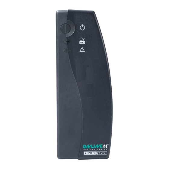
Seite 14: Abbildung 3: Vorder- Und Rückansicht Yunto Q 700
Abbildung 3: Vorder- und Rückansicht YUNTO Q 700 YQ_manual_ger-eng-it_ 2009-09-29.doc 9/29/2009, S. Spitzley... -
Seite 15: Abbildung 4: Vorder- Und Rückansicht Yunto Q 1250
Abbildung 4: Vorder- und Rückansicht YUNTO Q 1250 YQ_manual_ger-eng-it_ 2009-09-29.doc 9/29/2009, S. Spitzley... - Seite 16 User Manual (YUNTO Q450, YUNTO Q700, YUNTO Q1250) Germany Italy Switzerland Online USV-Systeme AG Online UPS Systems S.r.l. Online USV-Systeme AG Promenadeplatz 12 Via Edison 12 Industriestrasse 26 D-80333 München I-20058 Villasanta (MI) CH-8604 Volketswil Tel: +41-(0)1-9452829 Tel: +49-(0)89-2423990-10 TEL:+39-(0)39-2051444...
- Seite 17 List of Figures Figure 1: Connection of the UPS ……………………………………………….23 Figure 2: Front and back view of YUNTO Q450 ……………………………...28 Figure 3: Front and back view of YUNTO Q700 ………………………...……29 Figure 4: Front and back view of YUNTO Q1250 …………………………….30 YQ_manual_ger-eng-it_ 2009-09-29.doc...
-
Seite 18: Introduction
1. Introduction The ONLINE YUNTO Q-Series is a newly developed line interactive UPS (uninterruptible power supply). It provides perfect protection for personal computers against power failures. It also provides spike suppression and line noise filtering to protect critical equipment. 2. Safety Instructions... - Seite 19 Installation • Connect the UPS system only to socket outlet with earthing contact (Schuko-socket outlet). • The building wiring socket outlet (Schuko-socket outlet) must be easily accessible and close to the UPS system. • Use only VDE-approved, CE-marked power cable (e.g. the power cable of your computer) to connect the UPS system to the building wiring socket outlet (Schuko-socket outlet).
- Seite 20 Maintenance, servicing and faults • The UPS system operates with hazardous voltages. Only qualified maintenance personnel may carry out repairs. • Caution - risk of electric shock. Even after the unit is disconnected from the mains power supply (building wiring socket outlet), components inside the UPS system are still connected to the battery and are still electrically live and dangerous.
-
Seite 21: Indicators And Operating Controls
3. Indicators and Operating Controls The front panel LEDs and audio beeps indicate the UPS status. Switch and LEDs Symbol Function On/Off Turn the UPS system on and off. Status-LED 1. Steady: Input power is acceptable, (green) the UPS is in normal mode (online). 2. -
Seite 22: Installation And Start Up
4. Installation and Start Up 1) Inspect the packaging carton and its contents for damage. Please inform the transport agency immediately should you find signs of damage. Please keep the packaging in a safe place for future use. 2) Plug the UPS into a wall outlet (see figure 1), and press the on the front panel, then the UPS come into work. -
Seite 23: Figure 1: Connection Of The Ups
AC OUTPUT AC INTPUT 230V~ 50/60Hz 230~ 50/60Hz Relay Inverter DC Converter Charger CNTL 70X3 Interface MAIN BLOCK DIAGRAM Figure 1: Connection of the UPS YQ_manual_ger-eng-it_ 2009-09-29.doc 9/29/2009, S. Spitzley... -
Seite 24: Troubleshooting
5. Troubleshooting If the UPS system does not operate correctly, please attempt to solve the problem using the table below. Problem Possible cause Remedy indication, No input voltage Check building wall outlet and beep even UPS is mains cable by connecting connected to mains another device with this cable power supply... - Seite 25 Please keep the following information ready at hand before calling your dealer: 1. Model number, serial number 2. Date on which the UPS problem occurred 3. Detailed description of the problem YQ_manual_ger-eng-it_ 2009-09-29.doc 9/29/2009, S. Spitzley...
-
Seite 26: Technical Data
6. Technical data 6.1 Electrical specifications Model number YUNTO Q450 YUNTO Q700 YUNTO Q1250 INPUT Voltage 230 VAC (197 - 262 VAC) 50 Hz ± 4Hz ; 60Hz±4Hz Frequency Amperage 2.6 A 4.0 A 7.0 A (maximum) Phase 1ψ 2W, Ground... -
Seite 27: Typical Stored Energy Time (Battery Mode)
Dimensions Net Weight( Gross W x H x D (mm) Weight( kg) YUNTO Q 450 80*180*235 YUNTO Q 700 80*180*235 YUNTO Q1250 95*240*285 6.4 Operating environment Operation Temperature: 0 °C to 40 °C Storage Temperature: -15 °C to 40 °C... -
Seite 28: Appendix
7. Appendix Figure 2: Front and back view of YUNTO Q 450 YQ_manual_ger-eng-it_ 2009-09-29.doc 9/29/2009, S. Spitzley... -
Seite 29: Figure 3: Front And Back View Of Yunto Q700
Figure 3: Front and back view of YUNTO Q 700 YQ_manual_ger-eng-it_ 2009-09-29.doc 9/29/2009, S. Spitzley... -
Seite 30: Figure 4: Front And Back View Of Yunto Q1250
Figure 4: Front and back view of YUNTO Q 1250 YQ_manual_ger-eng-it_ 2009-09-29.doc 9/29/2009, S. Spitzley... - Seite 31 Manuale per l’Utente (YUNTO Q 450, YUNTO Q 700, YUNTO Q 1250) Germania Italia Swizzera Online USV-Systeme AG Online UPS Systems S.r.l. Online USV-Systeme AG Promenadeplatz 12 Via Edison 12 Industriestrasse 26 D-80333 München I-20058 Villasanta (MI) CH-8604 Volketswil Tel: +49-(0)89-2423990-10...
- Seite 32 Figura 1: Collegamento d ell'UPS …………………………………………….. 40 Figura 2: Vista frontale e posteriore del gruppo YUNTO Q 450……………..46 Figura 3: Vista frontale e posteriore del gruppo YUNTO Q 700……………..47 Figura 4: Vista frontale e posteriore del gruppo YUNTO Q 1250……………48 YQ_manual_ger-eng-it_ 2009-09-29.doc...
-
Seite 33: Introduzione
1. Introduzione La serie ONLINE YUNTO Q è una nuova famiglia di gruppi di continuità (UPS) progettati secondo la tecnologia line interactive, completamente controllati a microprocessore. Assicura una protezione perfetta contro le cadute di tensione, specialmente per personal computer e piccoli server. - Seite 34 Installazione • L’UPS è concepito per il funzionamento in luoghi chiusi, al riparo dalle intemperie. • Se l’UPS viene portato da ambiente molto freddo nel locale di lavoro può verificarsi un fenomeno di condensa. Prima della messa in funzione l’UPS deve essere assolutamente asciutto, va quindi rispettato un periodo di acclimatazione di almeno due ore.
- Seite 35 Funzionamento • ATTENZIONE: non estrarre il cavo di alimentazione dall'UPS o dalla presa di rete (presa di sicurezza dotata di messa a terra) durante il funzionamento perché altrimenti il collegamento a massa dell'UPS e di tutti i carichi ad esso allacciati verrebbero interrotti. Le apparecchiature connesse verrebbero dunque a perdere la protezione di terra in caso di cortocircuiti verso massa, con conseguente pericolo di folgorazione.
- Seite 36 • Le batterie possono causare folgorazioni e presentano elevate correnti di corto circuito. Per ogni operazione sulle batterie occorre essere a conoscenza e rispettare le seguenti regole e misure di sicurezza, così come ogni altra precauzione necessaria quando si lavori con delle batterie o con dei gruppi di continuità: a.
-
Seite 37: Comandi E Indicatori
3. Comandi e Indicatori Le indicazioni sullo stato di funzionamento del gruppo sono evidenziate per mezzo dei LED del pannello frontale, e per mezzo di segnali acustici. Tasti e indicatori Simbolo Funzione luminosi (LED) Premendo il tasto l'UPS può venire On/Off acceso e spento. - Seite 38 Segnali acustici Funzione (Bip) Segnale continuo Gruppo in fase di avvio. per 2 secondi 1 bip ogni 4 Caduta di tensione (blackout) Il gruppo funziona in secondi modo batteria. Il gruppo funziona in modo batteria e la carica della 1 bip ogni batteria è...
-
Seite 39: Installazione E Messa In Funzione
4. Installazione e messa in funzione 1) Al ritiro del gruppo esaminare accuratamente il cartone di imballaggio e il contenuto per scoprire eventuali danneggiamenti. Se si dovessero rilevare dei danni, avvisare lo spedizioniere e ritirare la merce con riserva. Conservare con cura l'imballaggio per utilizzi futuri: nel caso il gruppo dovesse essere reso, sarà... - Seite 40 AC OUTPUT AC INTPUT 230V~ 50/60Hz 230~ 50/60Hz Relay Inverter DC Converter Charger CNTL 70X3 Interface MAIN BLOCK DIAGRAM Figura 1: Collegamento dell'UPS YQ_manual_ger-eng-it_ 2009-09-29.doc 9/29/2009, S. Spitzley...
-
Seite 41: Risoluzione Degli Eventuali Problemi
5. Risoluzione degli eventuali problemi Se il gruppo sembra non funzionare correttamente, riferirsi alla tavola qua sotto per risolvere il problema. Problema Possibile causa Rimedio Nessuna Controllare la presa e il cavo indicazione, Non c'è tensione in di alimentazione,connettendo nessun segnale ingresso eventualmente un'altra acustico, anche... - Seite 42 Il LED verde é acceso, il LED Guasto nella ricarica rosso lampeggia, Contattare il fornitore della batteria 2 bip ogni 2 secondi Staccare dall'UPS Il LED verde é l'apparecchiatura alimentata acceso, Condizione di finché l'allarme acustico lampeggia, sovraccarico. termina. Ridurre il carico. 1 bip ogni mezzo secondo Disconnettere il carico e...
-
Seite 43: Specifiche Tecniche
6. Specifiche tecniche Caratteristiche elettriche Modello YUNTO Q 450 YUNTO Q 700 YUNTO Q 1250 INGRESSO Tensione 230 Vac (197 - 262 Vac.) 50 Hz ±4 Hz / 60 Hz ±4 Hz Frequenza Corrente 2.6 A 4.0 A 7.0 A... -
Seite 44: Autonomie Tipiche
Autonomie tipiche (funzionamento a batteria) Valori tipici a 25°C in minuti. Modello Carico 100% Carico 50% YUNTO Q 450 YUNTO Q 700 YUNTO Q 1250 Dimensioni e pesi Modello Dimensioni Peso Netto, Peso lordo, L x A x P (mm) - Seite 45 L'interfaccia RS-232 fa uso di un connettore Sub D a 9 piedini. La disposizione dei piedini é illustrata nella tabella sottostante Piedino Nome Funzione Dati ricevuti Dati trasmessi Massa YQ_manual_ger-eng-it_ 2009-09-29.doc 9/29/2009, S. Spitzley...
-
Seite 46: Appendice
7. Appendice Figura 2: Vista frontale e posteriore del gruppo YUNTO Q450 YQ_manual_ger-eng-it_ 2009-09-29.doc 9/29/2009, S. Spitzley... - Seite 47 Figura 3: Vista frontale e posteriore del gruppo YUNTO Q 700 YQ_manual_ger-eng-it_ 2009-09-29.doc 9/29/2009, S. Spitzley...
- Seite 48 Figura 4: Vista frontale e posteriore del gruppo YUNTO Q 1250 YQ_manual_ger-eng-it_ 2009-09-29.doc 9/29/2009, S. Spitzley...