Inhaltsverzeichnis
Werbung
Verfügbare Sprachen
Verfügbare Sprachen
Quicklinks
Werbung
Inhaltsverzeichnis
Fehlerbehebung

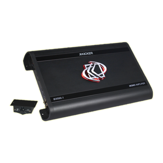
Inhaltszusammenfassung für Kicker BX350.1
- Seite 1 BX AMPLIFIER BX350.1 BX550.1 English Version Deutsche Version...
- Seite 2 BX.1-SERIES AMPLIFIERS Owner’s Manual MODEL: BX350.1 / BX500.1 Authorized KICKER Dealer: Purchase Date: Model Number: Serial Number: PERFORMANCE Model: BX350.1 BX550.1 RMS Power, all channels driven @ 14.4V, 4Ω ≤ 1% THD+N 200W x 1 300W x 1 @ 14.4V, 2Ω ≤ 1% THD+N...
-
Seite 3: Installation
INSTALLATION Mounting: Choose a structurally sound location to mount your KICKER amplifier. Avoid any damage of the vehicle’s components like wires, cables, board computer, seat belts, gastank where the screws be driven. Ensure that this chosen location provide sufficient air circulation for the amplifier. Do not mount the device into small or sealed spaces without air circulation near by heat dispersing parts or electrical parts of the vehicle. - Seite 4 OPERATION WITH 2 SUBWOOFERS minimum impedance of 4 ohms each subwoofer woofer 1 woofer 2 signal out signal in DUAL VOICE COIL INSTALLATION One 2 x 2 ohm woofer wired in serial Coil 1 for a 4 ohm load 2 Ohms Coil 1 - Coil 2 2 Ohms...
-
Seite 5: Operation
OPERATION Xover Switch: Use the XOVER switch of the amplifier to set the internal crossover to LP/BP, HP (Subsonic) or OFF. When the switch is set to OFF, a full bandwidth signal will be amplified. Set the switch to HP if you want the amplifier’s internal crossover to serve as a highpass filter (SUBSONIC controller). -
Seite 6: Troubleshooting
There is a green POWER LED and a red PROTECTION LED on the end panel of your KICKER BX series amplifier. When the green LED is lit, this indicates the amplifier is turned on and the amplifier is functioning properly. When the red LED is lit, this indicates the amplifier is running in protection mode and a problem has occurred. - Seite 7 Improper connections can result in blown amplifier fuses as well as the failure of other critical systems in the vehicle. If you have more questions about the installation or operation of your new KICKER product, see the Authorized KICKER Dealer where you made your purchase or contact the domestic distributor in your country.
-
Seite 8: Technische Daten
VERSTÄRKER BX.1 SERIE Benutzerhandbuch MODELL: BX350.1 / BX550.1 Autorisierter KICKER-Händler: Kaufdatum: Verstärker-Modellnummer: Verstärker-Seriennummer: TECHNISCHE DATEN Model: BX350.1 BX550.1 RMS-Leistung, alle Kanäle betrieben @ 14.4V, 4Ω, ≤ 1% Gesamtklirrfaktor 200W x 1 300W x 1 @ 14.4V, 2Ω, ≤ 1% Gesamtklirrfaktor... -
Seite 9: Betrieb Mit 1 Tieftöner
INSTALLATION Befestigung: Wählen Sie für die Installation des KICKER-Verstärkers einen geeigneten Einbauort. Vergewissern Sie sich, dass keine Kabel, Leitungen und andere Komponenten des Fahrzeugs beim Bohren beschädigt werden. Vergewissern Sie sich, dass der Verstärker am Montageort genügend Kühlung erhält. Montieren Sie das Gerät nicht in zu kleine, abgeschlossene Gehäuse ohne Luftzirkulation, in die Nähe von wärmeabstrahlende... -
Seite 10: Betrieb Mit 2 Tieftönern
BETRIEB MIT 2 TIEFTÖNERN Mindestmpedanz von 4 Ohm pro Subwoofer Tieftöner 1 Tieftöner 2 Signalausgang Signaleingang INSTALLATION FÜR TIEFTÖNER MIT 2 SCHWINGSPULEN Ein 2 x 2 Ohm Tieftöner seriell geschaltet Schwingspule 1 im 4-Ohm-Betrieb 2 Ohm Schwingspule 1 - Schwingspule 2 2 Ohm Schwingspule 2 - Ein 2 x 4 Ohm Tieftöner... -
Seite 11: Betrieb
BETRIEB XOVER-Schalter: Verwenden Sie den XOVER-Schalter, um die interne Frequenzweiche auf HP, OFF oder LP/ BP einzustellen. Wenn der Schalter auf OFF steht, wird ein Signal mit voller Bandbreite verstärkt. Stellen Sie den Schalter auf HP, wenn Sie die interne Frequenzweiche des Verstärkers als Hochpassfilter (SUBSONIC Regler) verwenden wollen. -
Seite 12: Bxrc Basspegel-Fernbedienung Installation
BXRC BASSPEGEL-FERNBEDIENUNG INSTALLATION Gehäuse befestigen Telefonkabel PROBLEMBEHEBUNG Wenn der Verstärker nicht zu funktionieren scheint, sollten Sie zuerst offensichtliche Faktoren prüfen, wie durchgebrannte Sicherungen, schlechte oder fehlerhafte Verkabelung, inkorrekte Einstellung des XOVER- Schalters und der Verstärkungsregler etc. Am Gerät befindet sich eine grüne LED (POWER) sowie eine rote PROTECT-LED. - Seite 13 Falsche Anschlüsse können zu einem Durchbrennen der Verstärkersicherung und einem Ausfall anderer wichtiger Systeme im Fahrzeug führen. Wenn Sie weitere Fragen zur Installation oder zum Betrieb Ihres neuen KICKER-Produkts haben, setzen Sie sich bitte mit Ihrem autorisierten KICKER-Fachhändler in Verbindung. Falls Sie weitere Unterstützung zum Produkt benötigen, wenden Sie sich bitte an die Audio Design GmbH Support Hotline (KICKER Vertrieb Deutschland)
- Seite 14 Contact your International KICKER dealer or distributor concerning specific procedures for your country’s warranty policies. WARNING: KICKER products are capable of producing sound levels that can permanently damage your hearing! Turning up a system to a level that has audible distortion is more damaging to your ears than listening to an undistorted system at the same volume level.
- Seite 15 BX AMPLIFIERS...
- Seite 16 Distribution: Audio Design GmbH Am Breilingsweg 3, D-76709 Kronau Tel. +49(0)7253-9465-0, Fax +49(0)7253-9465-10 www.audiodesign.de/kicker ©2010, All Rights Reserved , Printed in China...


