
Verwandte Anleitungen für MGE UPS Systems Pulsar Evolution 3000

Inhaltszusammenfassung für MGE UPS Systems Pulsar Evolution 3000
- Seite 1 www.mgeups.com SYSTEMS Pulsar Evolution 2200/3000/3000 XL Installation and user manual - Page 1 34007115EN/AA...
- Seite 2 Page 2 - 34007115EN/AA...
- Seite 3 Pulsar Evolution at the end of its service life. To discover the entire range of MGE UPS SYSTEMS products and the options available for the Pulsar Evolution range, we invite you to visit our web site at www.mgeups.com or contact your MGE UPS SYSTEMS representative.
-
Seite 4: Using This Document
Foreword Using this document Information may be found in two ways, using: the contents; the index. Pictograms Important instructions that must always be followed. Information, advice, help. Visual indication. Action. Audio indication. In the illustrations on the following pages, the symbols below are used: LED off. -
Seite 5: Inhaltsverzeichnis
Contents Presentation Overall view ..........................7 Tower position ..........................7 Rack position ..........................7 Back ............................. 8 Control panel ..........................9 Installation Unpacking and parts check ....................... 10 Upright installation (tower position) ..................11 Flat installation (rack position) ....................12 Connecting the protected equipment .................. - Seite 6 Contents Appendices Technical data ..........................24 Simplified diagram ........................24 Technical characteristics ....................... 25 Examples of battery backup times ....................26 Glossary ............................27 Index ............................. 28 Page 6 - 34007115EN/AA...
-
Seite 7: Presentation
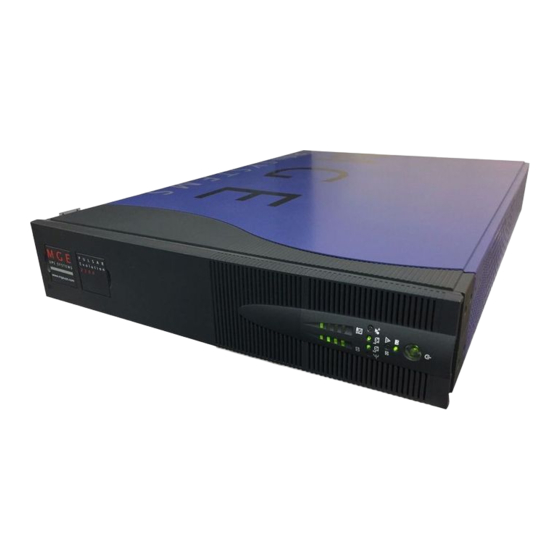
1. Presentation 1.1 Overall view Tower position Dimensions in mm (W x H x D) Evolution 2200 438 x 87.9 x 640 Evolution 3000 (19") (2U) Evolution 3000 XL Weight in kg Evolution 2200 Evolution 3000 Evolution 3000 XL Rack position - Page 7 34007115EN/AA... -
Seite 8: Back
TO BATTERY CABINET additional battery module. Data-line protection. Slot for communications-card option. Connector for an additional battery module. Pulsar Evolution 3000 / 3000 XL Output circuit breakers. Four outlets for direct connection of RS232 DATA LINE PROTECTION protected equipment. TO BATTERY... -
Seite 9: Control Panel
1. Presentation 1.3 Control panel Iluminated ON/OFF button for the outlets. Operation on battery power. UPS fault. Battery fault. Overload. Group 1 programmable outlets supplied with power. Group 2 programmable outlets supplied with power. Booster or fader mode. Bargraph indicating percent load at output. Bargraph indicating the battery charge level. -
Seite 10: Installation
2. Installation 2.1 Unpacking and parts check Cord for connection to the AC-power source for 3000/3000 XL versions only (for the 2200 version, use the power cord of the protected equipment). Two cords for connection of the protected equipment. RS232 communications cable. USB communications cable. -
Seite 11: Upright Installation (Tower Position)
2. Installation 2.2 Upright installation (tower position) Connect the two supports for the upright position. S A R P U L ti o n E v o lu 3 0 0 - Page 11 34007115EN/AA... -
Seite 12: Flat Installation (Rack Position)
2. Installation 2.3 Flat installation (rack position) Follow steps 1 to 6 for rack mounting of the UPS on the rails. The rails and the necessary mounting hardware are supplied by MGE UPS SYSTEMS. Page 12 - 34007115EN/AA... -
Seite 13: Connecting The Protected Equipment
As soon as the UPS is energised, the battery begins charging. Eight hours are required to charge to the full rated backup time. Pulsar Evolution 3000 XL: At least one EXB additional battery module must be connected to the UPS because it does not have internal batteries. See the EXB battery-module installation manual (Doc. no. 3400711600) for information on making the connections. -
Seite 14: Connection To The Rs232 Or Usb Communications Port (Optional)
RS232 2 or USB 1 communications port on the UPS. The UPS can now communicate with all MGE UPS SYSTEMS supervision, set-up or safety software. 2.6 Connection to the data-line protection port (optional) The data-line protection function on the UPS eliminates overvoltages flowing on the computer-network lines. -
Seite 15: Installation Of The Communications-Card Option
2. Installation 2.7 Installation of the communications-card option 1 - Remove the slot cover 5 secured by two screws. 2 - Insert the card in the slot. 3 - Secure the cover with the two screws. Slot for the communications-card option. -
Seite 16: Operation Start-Up
3. Operation 3.1 Start-up Press the ON / OFF button 15 . The buzzer beeps and all the LEDs come ON. The buzzer beeps twice during the self-test, then button 15 remains ON, indicating that the outlets are supplied with power. - AC power is present: Only button 15 is ON. -
Seite 17: Operation On Battery Power (Following Failure Of Ac-Input Power)
3. Operation 3.3 Operation on battery power (following failure of AC-input power) Transfer to battery power The AC-input power is out of tolerances, LED 16 goes ON. During operation on battery power, the buzzer beeps every ten seconds. The equipment connected to the UPS is supplied by the battery. Threshold for the low-battery warning When the threshold is reached, the buzzer beeps every three seconds. -
Seite 18: Personalisation (Optional)
3. Operation 3.4 Personalisation (optional) Function Personalisation parameters can be set and modified using the UPS Driver software installed on a computer that is connected to the UPS (see section 2.5 Connection to the RS232 communications port). Check that the RS232 26 communications cable is connected. UPS Driver installation: 1 - Insert the Solution-Pac CD-ROM containing the UPS Driver software in the drive of a PC running Windows. -
Seite 19: Voltage-Thresholds Tab
3. Operation Voltage-thresholds tab Configurable function Default setting Options Output voltage on battery power 230 V 200 V - 220 V - 240 V Upper threshold for transfer to battery power 294 V 271 to 294 V Fader-mode cut-in threshold 265 V 244 to 265 V Booster-mode cut-in threshold... -
Seite 20: Maintenance Trouble-Shooting
LED 17 flashes. A battery fault was detected during the automatic Replace the battery module (see battery test. section 4.2). Troubleshooting not requiring MGE UPS SYSTEMS after-sales support (3000/3000 XL versions only) Indication Signification Correction The outlets are not One of the output-protection circuit breakers 7... -
Seite 21: Replacement Of The Battery Module
4. Maintenance 4.2 Replacement of the battery module Safety rules Batteries constitute a danger (electrical shock, burns). The short-circuit current may be very high. Precautions must be taken for all handling: remove all watches, rings, bracelets and any other metal objects; use tools with insulated handles. - Seite 22 4. Maintenance F - Remove the screw securing the battery cover. G - Remove the cover. H - Disconnect the battery module. I - Remove the battery module. Installation of the new battery module Carry out the above operation in reverse order. To maintain an identical level of performance and safety, use a battery module identical to that previously mounted in the UPS.
-
Seite 23: Environment
UPS recycling at the end of service life: MGE UPS SYSTEMS undertakes to recycle, by certified companies and in compliance with all applicable regulations, all UPS products recovered at the end of their service life (contact your MGE branch office). -
Seite 24: Technical Data
6. Appendices 6.1 Technical data Simplified diagram Filter Booster / fader transformer Input Output Inverter Charger Battery Page 24 - 34007115EN/AA... -
Seite 25: Technical Characteristics
6. Appendices Technical characteristics Pulsar Evolution 2200 Pulsar Evolution 3000 Pulsar Evolution 3000 XL Output rating 2200 VA / 1540 W 3000 VA / 2000 W 3000 VA / 2000 W AC-input power Voltage Single-phase, 160 V to 294 V Frequency 47 Hz to 70 Hz (50 Hz system) or 56.5 Hz to 70 Hz... -
Seite 26: Examples Of Battery Backup Times
+ 1 hard disk 4 distributed servers + 1 hub + 1 router 12 rack-mounted servers t (min) Pulsar Evolution 3000 XL + 3 EXB 1 telecom device 1 set of telecom devices 1 large set of telecom devices t (min) -
Seite 27: Glossary
These outlets may be programmed using the Solution-Pac software on the CD-ROM supplied with the UPS. Solution-Pac MGE UPS SYSTEMS safety, set-up and supervision software suite on the CD-ROM supplied with the UPS. Uninterruptible Power Supply. UPS Driver Communications software on the CD-ROM supplied with the UPS. -
Seite 28: Index
6. Appendices 6.3 Index Automatic start ............... 18 LEDs ................9 Bargraph ................9 Mode Battery Booster mode ............. 9, 16 Additional modules ........... 8 Fader mode ............9, 16 Backup time ............26 Sleep mode (automatic start) ......... 18 End of backup time .......... - Seite 29 3400711500/AA...
- Seite 30 www.mgeups.com SYSTEMS Pulsar Evolution 2200/3000/3000 XL Installations- und Bedienungsanleitung - Seite 1 34007115DE/AA...
- Seite 31 Seite 2 - 34007115DE/AA...
-
Seite 32: Einleitung
Einleitung Wir danken Ihnen, daß Sie sich für ein Produkt von MGE UPS SYSTEMS zur sicheren Stromversorgung Ihrer Systeme entschieden haben. Die Baureihe Pulsar Evolution wurde mit größter Sorgfalt entwickelt. Um die Leistungen Ihrer USV (Unterbrechungsfreien Stromversorgung) optimal nutzen zu können, empfehlen wir Ihnen, sich ein wenig Zeit zu nehmen und die vorliegende Anleitung aufmerksam zu lesen. -
Seite 33: Vorbemerkungen
Vorbemerkungen Aufbau der Installations- und Bedienungsanleitung Die Suche nach bestimmten Informationen erfolgt auf einfachste Weise: über das Inhaltsverzeichnis, über das Stichwortregister. Bedeutung der Piktogramme WICHTIG, Hinweise unbedingt befolgen. Informationen, Ratschläge, Hilfen. Optische Anzeige. Maßnahmen, Handlungen. Akustischer Alarm. In den Abbildungen der nachfolgenden Seiten sind die LED-Anzeigen mit folgenden Symbolen dargestellt: LED AUS. - Seite 34 Inhalt Ansichten und Beschreibung Gesamtansicht ..........................7 Toweraufstellung ..........................7 Rackmontage ..........................7 Rückansicht ..........................8 Anzeige- und Bedienfeld ......................9 Aufstellung und Installation Entfernen der Verpackung und Überprüfung des Lieferumfangs .......... 10 Tower- Modell ..........................11 Rack-Modell ..........................12 Anschluß...
- Seite 35 Inhalt Anhang Technische Daten ........................24 Blockschaltbild ..........................24 Kenndaten ............................. 25 Beispiele für Batterie-Autonomiezeiten ..................26 Fachbegriffe ..........................27 Stichwortregister ........................28 Seite 6 - 34007115DE/AA...
-
Seite 36: Ansichten Und Beschreibung
1. Ansichten und Beschreibung 1.1 Gesamtansicht Toweraufstellung Abmessungen in mm (B x H x T) Evolution 2200 438 x 87,9 x 640 Evolution 3000 (19") (2TE) Evolution 3000 XL Gewicht in kg Evolution 2200 Evolution 3000 Evolution 3000 XL Rackmontage - Seite 7 34007115DE/AA... -
Seite 37: Rückansicht
Stecker zur automatischen Erkennung TO BATTERY CABINET eines externen Batteriemoduls. Datenleitungsschutz. Steckplatz für Kommunikationskarte (Option). Steckverbinder zum Anschluß eines Pulsar Evolution 3000 / 3000 XL externen Batteriemoduls. Ausgangsschalter. RS232 DATA LINE PROTECTION Gruppe mit 4 normalen (nicht programmierbaren) TO BATTERY CABINET Ausgangssteckdosen. -
Seite 38: Anzeige- Und Bedienfeld
1. Ansichten und Beschreibung 1.3 Anzeige- und Bedienfeld EIN/AUS-Taster (ON/OFF) mit LED zur Freischaltung/Trennung der Ausgangssteckdosen. Batteriebetrieb. USV-Störung. Batteriestörung. Überlast. Programmierbare Steckdosengruppe 1 an Spannung. Programmierbare Steckdosengruppe 2 an Spannung. Booster- oder Fader-Modus. Balkenanzeige Auslastungsgrad. Balkenanzeige Batterieladezustand. 76 bis 100%. 51 bis 75%. -
Seite 39: Aufstellung Und Installation
2. Aufstellung und Installation 2.1 Entfernen der Verpackung und Überprüfung des Lieferumfangs Netzkabel für Modelle 3000/3000 XL (bei Modell 2200 Verbraucher-Netzkabel verwenden). 2 Verbraucher-Anschlußkabel. RS232-Schnittstellenkabel. USB-Schnittstellenkabel. Montagekit für Einbau in 19"-Schränke. 2 Verriegelungsabdeckung für Verbraucher-Anschlußkabel. CD ROM mit USV-Software "Solution Pac" und "UPS Driver". Dokumentation. -
Seite 40: Toweraufstellung
2. Aufstellung und Installation 2.2 Toweraufstellung Montage der Stützfüße. S A R P U L ti o n E v o lu 3 0 0 - Seite 11 34007115DE/AA... -
Seite 41: Rackeinbau
2. Aufstellung und Installation 2.3 Rackeinbau Montage und Befestigung der Teleskopschienen für Rackeinbau (Schritte 1 bis 6 befolgen) Befestigungsschrauben und Teleskopschienen liegen dem Gerät bei. Seite 12 - 34007115DE/AA... -
Seite 42: Anschluß Der Verbraucher
Nach dem erstmaligen Netzanschluß der USV benötigt das Gerät eine Ladezeit von mindestens 8 Stunden, um die volle Autonomiezeit der Batterie zur Verfügung zu stellen. Pulsar Evolution 3000 XL : Dieses Modell wird ohne interne Batterien geliefert und muß daher an mindestens ein externes Batteriemodul EXB angeschlossen werden. Anschlußhinweise siehe Installationsanleitung Nr. 3400711600 des Batteriemoduls EXB. -
Seite 43: Anschluß Des Kommunikationskabels Für Rs232- Bzw. Usb-Schnittstelle (Wahlweise)
2 - Kabel 26 bzw. 27 mit dem anderen Ende an die RS232-Schnittstelle 2 oder den USB-Port 1 der USV anschließen. Die USV kann nun über verschiedene Softwarepakete von MGE UPS SYSTEMS mit dem angeschlossenen Rechnersystem kommunizieren (Überwachung, Konfiguration, Sicherheitsparameter). -
Seite 44: Einbau Einer Kommunikationskarte (Option)
2. Aufstellung und Installation 2.7 Einbau einer Kommunikationskarte (Option) 1 - Abdeckung 5 durch Herausdrehen der zwei Schrauben von der USV lösen. 2 - Karte in den Steckplatz einstecken. 3 - Karte mit den zwei Schrauben befestigen. Steckplatz für Kommunikationskarte. Die Kommunikationskarten können bei eingeschalteter USV installiert werden. -
Seite 45: Betriebszustände
3. Betriebszustände 3.1 Inbetriebnahme EIN/AUS-Taste 15 drücken. Der Summer ertönt kurz, und sämtliche LEDs leuchten gleichzeitig auf. Während des anschließenden Selbsttests ertönt der Summer zweimal. Die LED der Drucktaste 15 leuchtet kontinuierlich und zeigt an, daß die Ausgangssteckdosen versorgt werden. - Einspeisenetz vorhanden: Nur die LED der EIN/AUS-Taste 15 leuchtet. -
Seite 46: Batteriebetrieb (Bei Netzausfall)
3. Betriebszustände 3.3 Batteriebetrieb (bei Netzausfall) Umschaltung auf Batteriebetrieb Verläßt das Einspeisenetz den zulässigen Toleranzbereich, schaltet die USV auf Batteriebetrieb und die LED 16 leuchtet auf. Während des Batteriebetriebs ertönt alle 10 Sekunden ein akustisches Signal. Die an die USV angeschlossenen Verbraucher werden unterbrechungsfrei über die Batterie weiter versorgt. -
Seite 47: Kundenspezifische Anpassung Per Software (Wahlweise)
3. Betriebszustände 3.4 Kundenspezifische Anpassung per Software (wahlweise) Software, Installation und Funktion Die kundenspezifische Anpassung der USV kann mit Hilfe der Software "UPS Driver" über einen Rechner erfolgen, der über die serielle RS232-Schnittstelle mit der USV verbunden ist (siehe Abschnitt 2.5). Vorhandensein der RS232- 26 Verbindung überprüfen. -
Seite 48: Registerkarte "Spannungsgrenzwerte
3. Betriebszustände Registerkarte "Spannungsgrenzwerte" Einstellungen Default-Einstellung Kundenspezifische Anpassung Ausgangsspannung (Batteriebetrieb) 230 V 200 V - 220 V - 240 V Oberer Spannungsgrenzwert für 294 V 271 bis 294 V Umschaltung auf Batterie Grenzwert für Einschaltung des Fader-Modus’ 265 V 244 bis 265 V Grenzwert für Einschaltung des Booster-Modus’... -
Seite 49: Wartung Und Service
4. Wartung und Service 4.1 Fehlerbehebung Fehlerbehebung ohne Inanspruchnahme des MGE-Kundendienstes (alle Modelle) Fehleranzeige Fehlerursache Fehlerbehebung LED 18 blinkt und Überlastung der USV. Die Leistungsaufnahme der Leistungsaufnahme der Summer ertönt. angeschlossenen Verbraucher übersteigt die angeschlossenen Systeme Nennleistung der USV. überprüfen und weniger wichtige Verbraucher abschalten. -
Seite 50: Austausch Des Batteriemoduls
4. Wartung und Service 4.2 Austausch des Batteriemoduls Sicherheitsmaßnahmen: Die Batterie hat einen hohen Kurzschlußstrom und kann Stromschläge verursachen. Bei jeder Handhabung der Batterien sind daher folgende Sicherheitsmaßnahmen einzuhalten: Armbanduhren, Ringe, Armreifen und sonstige an Händen oder Armen getragene Metallgegenstände abnehmen. Werkzeuge mit Isoliergriff verwenden. - Seite 51 4. Wartung und Service F - Befestigungsschraube der Batterieabdeckung lösen. G - Abdeckung entfernen. H - Batteriemodul durch Lösen der Steckverbindung abklemmen. I - Batteriemodul herausziehen und durch neues ersetzen. Einbau des neuen Batteriemoduls Die oben beschriebenen Handgriffe in umgekehrter Reihenfolge ausführen. Zur Gewährleistung der Sicherheit und des Betriebsverhaltens dürfen nur Austauschmodule verwendet werden, die mit den eingebauten Batterien baugleich sind.
-
Seite 52: Umweltschutz
Es enthält weder FKW- noch FCKW-Verbindungen. Recycling der USV nach Ablauf der Lebensdauer: MGE UPS SYSTEMS verpflichtet sich, sämtliche nach Ablauf der Lebensdauer rückgeführten Komponenten durch zugelassene Entsorgungsunternehmen einer Wiederverwertung gemäß den gesetzlichen Bestimmungen zuzuführen (wenden Sie sich bitte an Ihre MGE-Vertretung). -
Seite 53: Anhang
6. Anhang 6.1 Technische Daten Blockschaltbild Filter Booster-/Fader-Trafo Netz Verbraucher Gleichrichter/ Wechselrichter Ladegerät Batterie Seite 24 - 34007115DE/AA... -
Seite 54: Kenndaten
6. Anhang Kenndaten Pulsar Evolution 2200 Pulsar Evolution 3000 Pulsar Evolution 3000 XL Ausgangsleistung 2200 VA / 1540 W 3000 VA / 2000 W 3000 VA / 2000 W Einspeisenetz Spannung 160 bis 294 V , einphasig Frequenz 47 - 70 Hz (50-Hz-Netz) bzw. 56,5 - 70 Hz... -
Seite 55: Beispiele Für Batterie-Autonomiezeiten
Pulsar Evolution 3000 1 Datenserver + 1 Speicherplatte 4 verteilte Server + 1 Hub + 1 Router 12 Rack-Server t (min) Pulsar Evolution 3000 XL + 3 EXB 1 TK-System 1 TK-Anlage 1 TK-Großanlage t (min) Seite 26 - 34007115DE/AA... -
Seite 56: Fachbegriffe
6. Anhang 6.2 Fachbegriffe Ausgangsschalter Schalter zum Schutz der USV gegen starke verbraucherseitige Überlasten oder Störungen der angeschlossenen Verbraucher. Ausgangssteckdosen Pulsar Evolution verfügt abgangsseitig über eine Gruppe von 4 nicht programmierbaren Ausgangssteckdosen. Autonomiezeit Betriebsdauer des Geräts mit Verbraucherversorgung über die Batterie bei Ausfall des Einspeisenetzes. -
Seite 57: Stichwortregister
6. Anhang 6.3 Stichwortregister Abmessungen und Gewichte ........... 7 Kenndaten ..............25 Alarmton (Summer) ............17 Kommunikationskarte ..........8, 15 Anschlüsse Kundenspezifische Anpassung ........18 Datenleitung ............14 Ausgang ..............19 RS232-Schnittstelle ..........14 Batterie ..............18 USB-Schnittstelle ........... 14 Ein/Aus-Bedingungen ..........