
Verwandte Anleitungen für WEISS TC 120


Inhaltszusammenfassung für WEISS TC 120
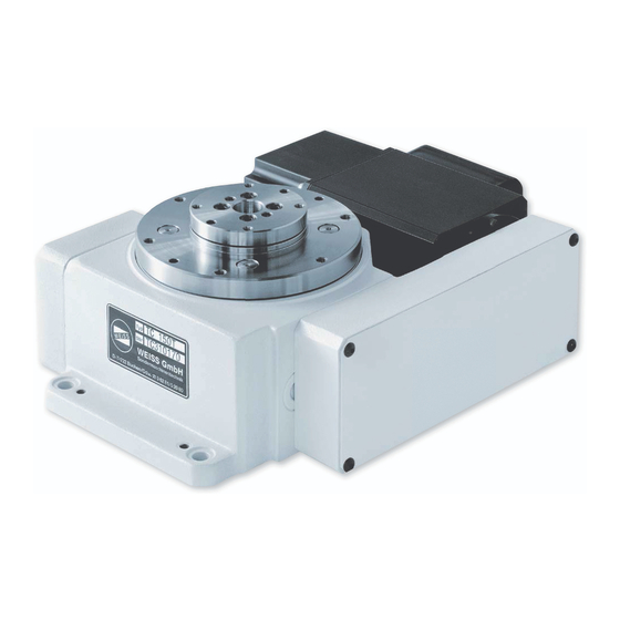
- Seite 1 Rundschalttische TC Rotary Indexing Tables TC Betriebsanleitung Operating Instructions...
- Seite 2 - Für Ihre Notizen - - For your Notes - WEISS GmbH 03/2002...
- Seite 3 +49 (0) 6281 / 5208-0 Fax: +49 (0) 6281 / 9150 Fax: +49 (0) 6281 / 9150 eMail: info@weiss-gmbh.de eMail: info@weiss-gmbh.de Internet: http://www.weiss-gmbh.de Internet: http://www.weiss-gmbh.de Technische Änderungen vorbehalten. We reserve the right to change or discontinue specifications without prior notice. WEISS GmbH 03/2002...
-
Seite 4: Inhaltsverzeichnis
EF 150/3, EF 220/3, EF 300/3 EF 150/3, EF 220/3, EF 300/3 Start-Up Inbetriebnahme Safety regulations Sicherheitsbestimmungen Electrical Preparations Elektrische Vorbereitungen Breather Valve Entlüftungsschraube/Verschlussstopfen General Start-Up Allgemeines Vorgehen zur Inbetrieb- nahme Installation of Tooling Plate Montage von Zusatzschalttellern WEISS GmbH 03/2002... - Seite 5 Troubleshooting the Control CArd EF xxx Rundschalttischsteuerung EF xxx Ersatzteile Spare Parts Entsorgung und Recycling Disposal and Recycling Anhang Appendix Zusatzinformationen Additional information Ringrundschalttische TR und NR Indexing Rings TR and NR Zusatzinformationen Additional information Ringrundschalttisch NR Indexing Ring NR WEISS GmbH 03/2002...
- Seite 6 - Für Ihre Notizen - - For your Notes - WEISS GmbH 03/2002...
-
Seite 7: Sicherheitsvorschriften
Gesamtanlage, integrated adheres to the control and safety in welche der Rundschalttisch integriert ist, regulations of “Machine Regulations sowie die Steuerung – speziell das 98/37/EG” Sicherheitssystem – der Maschinenrichtlinie 98/37/EG entspricht! WEISS GmbH 03/2002... - Seite 8 über die Gefahren unterrichtet sind. WARNUNG WARNING Es ist in keinem Fall möglich, den It is not possible to turn the indexer by Rundschalttisch von Hand in eine der hand in one of the dwell periods. möglichen Verriegelungspositionen zu drehen! WEISS GmbH 03/2002...
- Seite 9 Sie für das Befestigen des Rundschalttisches am Hebezeug Ringschrauben, die der Belastung sicher standhalten. Für TC 120 bis TC 320 genügen zwei Ring- Use 2 eyebolts for indexer models TC 120 to schrauben, ab TC 500 sind drei TC 320, use 3 eye bolts for models TC 500 Ringschrauben einzusetzen.
- Seite 10 +49 (0) 6281 / 9150 Fax: +49 (0) 6281 / 9150 eMail: info@weiss-gmbh.de eMail: info@weiss-gmbh.de Internet: http://www.weiss-gmbh.de Internet: http://www.weiss-gmbh.de Im Internet können Sie sämtliche Vertreter- You will find all addresses of our adressen abrufen. representatives on our web page. WEISS GmbH 03/2002...
-
Seite 11: Beschreibung Der Rundschalttische
Kurvenbahn der Antriebskurve (Rollreibung) During dwell two cam followers touch the ab. In der Verriegelungsphase liegen zwei groove under a preload. The cam followers Antriebsrollen vorgespannt an der have needle bearings. Antriebskurve an. Die Kurvenrollen sind nadelgelagert. Fig. 2-1 WEISS GmbH 03/2002... -
Seite 12: Antrieb
Drehbewegungszeit keine Fertigmeldung durch den induktiven Näherungsschalter "P" erfolgt. Bei Nichteinhaltung dieser Empfehlungen We will decline the warranty for the motor können wir keine Garantie für if this recommendation is not being Motorschäden übernehmen. followed. WEISS GmbH 03/2002... -
Seite 13: Einbaulagen Der Rundschalttische Und Anbau Des Motors (Antriebslage)
Fig. 2-2 Die aufgezeigten Möglichkeiten der The shown possibilities of the drive positions Antriebslagen sind für alle Einbaulagen der are acceptable for all mounting positions of Rundschalttische zulässig. the index tables. WEISS GmbH 03/2002... - Seite 14 230V / 50, 60 Hz (1 Phase); 0,075 A 230VAC / 50, 60 Hz (single phase); 0.075 A Der Motor des Fremdlüfters muss über eine The motor for the cooling fan needs a 0.1 A Sicherung 0,1 A mittelflink angeschlossen fuse. werden. WEISS GmbH 03/2002...
- Seite 15 (Fig.2-4). 2-3) oder direkt angefräst (Fig. 2-4). Aufgeschraubter Positionsnocken Boltet on cam (z.B. am TC 220): (i.e. TC 220) Fig. 2-3 Angefräster Positionsnocken Milled on cam (z.B. am TC 320): (i.e. TC 320) Fig. 2-4 WEISS GmbH 03/2002...
-
Seite 16: Dauermagnetbremse
2 million cycles (see nachgestellt werden (siehe Kapitel 5.1). chapter 5.1) Bei den Typen TC 120 und TC 150 Models TC 120 and TC 150 (version without (Ausführung ohne selbstnachstellende selfadjusting brake) use a brake that cannot Bremse) ist eine Bremse eingesetzt, die nicht be adjusted. -
Seite 17: Verändern Der Schaltzeit
Ihnen dann die benötigten Teile zusenden. Bei Austausch des Motors: To exchange the motor see chapter 5.3 siehe Kapitel 5.3. Bei Austausch des Zahnriemensatzes: To exchange the timing belt / pulley siehe Kapitel 5.4. combination see chapter 5.4. WEISS GmbH 03/2002... - Seite 18 - Für Ihre Notizen - - For your Notes - WEISS GmbH 03/2002...
-
Seite 19: Steuern Der Rundschalttische
Antrieb erst am Ende der Verriegelungsphase zum Stehen kommt. Der Näherungsinitiator muss aber But the limit switch still has to be noch sicher aktiv sein. activated. Linkslauf Rechtslauf Pendeln CCW rotation CW rotation Reciprocating Fig. 3-1 WEISS GmbH 03/2002... -
Seite 20: Steuern Mit Der Steuerkarte Ts 002 E
There will be a fault Der Antrieb muss innerhalb der message (“Position Overrun”) if the indexer Verriegelungsphase zum Stillstand kommen. the overruns the lock position. Dies wird von der Steuerkarte überwacht. Im Fehlerfall wird eine Störung nach außen gemeldet ("Position überfahren"). WEISS GmbH 03/2002... - Seite 21 Hand in eine der möglichen Verriegelungspositionen zu drehen! For additional information please consult the Für weitergehende Informationen konsultieren Manual for the electronic Control Card Sie bitte die Betriebsanleitung für die TS 002 E. elektronische Steuerkarte TS 002 E. WEISS GmbH 03/2002...
-
Seite 22: Steuern Mit Der Steuerung Ef
The best possible starting position is Anschließend ist die Stopprampe zu optimie- guaranteed in this way. ren bis der Positionsnocken auf der Antriebs- kurve kurz vor dem Ende der Verriegelungs- phase steht. Somit ist eine zeitoptimale Start- position erreicht. Fig. 3-5 WEISS GmbH 03/2002... - Seite 23 Hand in eine der möglichen Verriegelungspositionen zu drehen! For additional information please consult the Für weitergehende Informationen konsultieren Operation Manual for the Frequency Sie bitte die Betriebsanleitung für die Inverter EF-xxx. Rundtischsteuerungen EF-xxx. WEISS GmbH 03/2002...
-
Seite 24: Steuerungsablauf Mit Fremdsteuerung (Sps)
Start signal for assembly steps Stoppverzögerungszeit Start of stop delay timer Nach Ablauf der Stoppverzögerungszeit After stop delay time Motorschütz: Motor contactor: Bremse: Brake: „P“ aktiv “P”: Active Ü Ü Antriebskurve steht, Teller steht Cam stopped, dial locked WEISS GmbH 03/2002... - Seite 25 Regel ein Hinweis darauf, dass brake has to be adjusted (see chapter 5.1) die Bremse nachgestellt werden muss or that the motor contactor (brake motors) has (siehe Kapitel 5.1) oder der Motorschütz (bei worn out. Bremsmotoren) verschlissen ist. WEISS GmbH 03/2002...
-
Seite 26: Anschluss Von Steuerung
Bremsmotor Normalbetrieb (24 V Bremse) Brake Motor Normal Operation (24 V Brake): Fig. 3-6 Motorschutzschalter Protective motor switch K0.1, K0.2: Notausrelais K0.1, K0.2: E-STOP Relay Elektronischer Motorschütz Electronic Motor Contactor Rundschalttischmotor Index Table Motor Bremse Brake Initiator Position Limit Switch Position WEISS GmbH 03/2002... -
Seite 27: Bremsmotor Pendelbetrieb (24V Bremse)
Polung der beiden adjusting magnetic brake (KOBOLD motor). Bremsanschlüsse geachtet werden. Die The polarity of the brake connections is Polarität der Bremsanschlüsse ist im printed in the terminal box of the motor. Motorklemmbrett aufgedruckt. WEISS GmbH 03/2002... - Seite 28 (see Fig. 3-6 and 3-7). Bei Einsatz der 230V-Wechselstrombremse If you use a 230VAC brake it's not possible to ist die Ansteuerung des Motors über einen operate the motor with a frequency inverter! Frequenzumrichter nicht möglich! WEISS GmbH 03/2002...
-
Seite 29: Schaltungsbeispiel Für Langsamlaufende Rundschalttische
Schaltungsbeispiel für langsamlaufende Example for slow cycling indexing tables Rundschalttische Fig. 3-8 Motorschutzschalter Protective motor switch K0.1, K0.2: Notausrelais K0.1, K0.2: E-STOP Relay Motorschütz Motor Contactor Rundschalttischmotor Index Table Motor Bremse Brake Bremsgleichrichter Rectifier for brake circuit WEISS GmbH 03/2002... -
Seite 30: Schaltungsbeispiel Für Schnelllaufende Rundschalttische
Welche der beiden Varianten für Ihren Rund- You can find the option, which was used, for schalttisch gewählt wurde, entnehmen Sie your application on the order confirmation, on bitte der Auftragsbestätigung, dem the shipping papers or on the invoice. Lieferschein oder der Rechnung. WEISS GmbH 03/2002... -
Seite 31: Anschluss Der Steuerung Ef 037/1
O7: Tisch in Position I9: /RESET O7: indexer in Position I10: Positionssensor I10: Limit switch Position I11: Start (Flanke) I11: Start (edge) I12: Start (Pegel) I12: Start (level) I13: Drehrichtung I13: Direction of rotation (CW / CCW) (CW / CCW) WEISS GmbH 03/2002... -
Seite 32: Anschluss Der Steuerungen
O7: Tisch in Position I9: /RESET O7: indexer in Position I10: Positionssensor I10: Limit switch Position I11: Start (Flanke) I11: Start (edge) I12: Start (Pegel) I12: Start (level) I13: Drehrichtung I13: Direction of rotation (CW / CCW) (CW / CCW) WEISS GmbH 03/2002... -
Seite 33: Inbetriebnahme
Belastung gemäss nachstehender Gewichtstabelle sicher standhalten. Für TC 120 bis TC 320 genügen zwei Ring- Use 2 eyebolts for indexer models TC 120 to schrauben (Fig. 4-1), ab TC 500 sind drei TC 320 (see Fig. 4.1), use 3 eye bolts for Ringschrauben einzusetzen. -
Seite 34: Elektrische Vorbereitungen
Bremse zu schließen und message “Overload” in case the E-stop zweitens die zwangsläufig auftretende occurs during the index period. Fehlermeldung "Motorüberlast" zu unter- drücken, falls die Motorspannungs- abschaltung mitten im Zyklus erfolgt. WEISS GmbH 03/2002... -
Seite 35: Entlüftungsschraube/Verschlussstopfen
If the indexer is installed in Unterseite eine zweite Entlüftungsbohrung another mounting position than ordered, there vorhanden. Entlüftungsschraube und is the possibility to change the breather valve Verschlussstopfen können dann getauscht and the plug. werden. WEISS GmbH 03/2002... -
Seite 36: Allgemeines Vorgehen Zur Inbetriebnahme
Beim Verstiften des Zusatzschalttellers die chamfered slightly before installation of the Stifte an der Einführseite leicht abpolieren und tooling plate. Use a light hammer to avoid gleichmässig mit kleinem Hammer loss of accuracy. einschlagen, um Genauigkeitsverluste zu vermeiden. WEISS GmbH 03/2002... -
Seite 37: Wartung
Die Rundschalttische der Typen TC 120 und The index tables Model TC 120 and TC 150 TC 150 sind mit Bremsmotoren ausgerüstet, have brake motors with a brake, which cannot deren Bremse nicht nachstellbar ist. Bei be adjusted. - Seite 38 Zum Verdrehen der Einstellstücke (2) die Be- loosen the bolts (1), to check the air gap you festigungsschrauben (1) lösen, zum Messen have to tighten the bolts. des Luftspaltes Befestigungsschrauben anzie- hen! Fig. 5-2 Fig. 5-3 0,2 – 0,3 mm WEISS GmbH 03/2002...
-
Seite 39: Bremse Ersetzen
Bremse ersetzen Replace Brake Die Bremse der Motoren für die Rundschalt- The brake on the TC 120 and TC 150 index tische der Typen TC 120 und TC 150 kann tables cannot be adjusted. After it is worn nicht nachgestellt werden. Bei Verschleiß ist out, it has to be replaced completely as deshalb die komplette Bremse gemäss... -
Seite 40: Motor Ersetzen
Disconnect the power from the motor. inbetriebsetzung durch Drittpersonen sichern! Vorgehen: How to proceed: Motor spannungslos schalten. Disconnect motor from power. Motor und Bremse abklemmen. Disconnect motor and brake. Abdeckblech des Zahnriemenkastens Remove timing belt cover. entfernen. WEISS GmbH 03/2002... - Seite 41 Motor und Bremse anklemmen. Rewire motor and brake 10. Probelauf durchführen. 10. Test run. 11. Zahnriemenspannung erneut prüfen 11. Re-check tension of timing belt. (siehe Kapitel 5.4). (Chapter 5.4) 12. Abdeckblech des Zahnriemenkastens 12. Install timing belt cover. anschrauben. WEISS GmbH 03/2002...
-
Seite 42: Zahnriemen Ersetzen
Mitte von Hand leicht um you can twist the belt by approx. 45° to 90° (in 45° bis 90° (je nach Riemenlänge) anstellen the middle between the 2 pulleys). lässt. Fig. 5-8 WEISS GmbH 03/2002... -
Seite 43: Näherungsinitiator Ersetzen
Rundschalttisches sowie teilweise von dessen its mounting position and gear ratio: Einbaulage und Getriebestufe ab: Typ / Type Menge / Quantity Menge / Quantity (Type T) (Type X) TC 120 150 ml 200 ml TC 150 150 ml 250 ml TC 220 300 ml... - Seite 44 - Für Ihre Notizen - - For your Notes - WEISS GmbH 03/2002...
-
Seite 45: Störungsbehebung
Short voltage peak at input Eingang "F" der “F” of the control card Steuerkarte (Nachweis (check with oscilloscope) durch Speicheroszilloskop) Maßnahme: Initiatorkabel räumlich To rectify: Re-route limit switch wiring anders verlegen oder or use shielded cabling abschirmen WEISS GmbH 03/2002... -
Seite 46: Fault Message "Motor Overload
Testlauf these two plates unterziehen Ursache: Zahnriemen defekt Cause: Defect timing belt Maßnahme: Zahnriemen auf Bruch To rectify: Check and possibly überprüfen, replace timing belt gegebenenfalls ersetzen (Chapter 5.4) (siehe Kapitel 5.4) WEISS GmbH 03/2002... -
Seite 47: Fault Message "Electrical Short
30 V (for short Ursache: Versorgungsspannung period) höher als 30 V (auch kurz- To rectify: Check the voltages, find zeitig) and eliminate reasons for Maßnahme: Spannung messen, the spikes Gründe für höhere Spannung eruieren und für Abhilfe sorgen WEISS GmbH 03/2002... -
Seite 48: Troubleshooting The Control Card Ef Xxx
Eingang I4 der SPS auf HIGH setzen r set input I4 of the PLC to HIGH r Eingang I9 der SPS auf LOW setzen (nur r set input I9 of the PLC to LOW (only if bei Konfiguration über W012) configures via W012) WEISS GmbH 03/2002... -
Seite 49: Ersatzteile
Ersatzteilen vorzubeugen, bitten wir Sie, in spare parts order, we would require the Ihren Ersatzteil-Bestellungen immer folgende following information: Daten anzugeben: r Seriennummer gemäss WEISS- Serial Number of the index table from the Typenschild am Rundschalttisch WEISS type plate r Bestellnummer des Ersatzteils gemäss Part numbers from the wear parts list Verschleißteilliste... - Seite 50 - Für Ihre Notizen - - For your Notes - WEISS GmbH 03/2002...
-
Seite 51: Entsorgung Und Recycling
If in doubt please contact your local Sammelstellen erteilen Ihnen Ihre lokalen authorities. Verwaltungsbehörden. Bei der Entsorgung müssen auf jeden Fall die In all cases you should adhere to the einschlägigen landesüblichen und regionalen respective laws. Gesetze und Richtlinien beachtet werden. WEISS GmbH 03/2002... - Seite 52 - Für Ihre Notizen - - For your Notes - Weiss GmbH 03/2002...
-
Seite 53: Transport
Die Ringrundschalttische TR und NR können The Indexing Rings TR and NR only can be ausschließlich in der Einbaulage NORMAL mounted in the NORMAL horizontal position (siehe Kapitel 2.3) eingesetzt werden, d.h. (refer to chapter 2.3)! waagerecht! WEISS GmbH 03/2002... - Seite 54 Sie bitte die Bohrungen holes "B" can be used. Drill through the „B“ als Zentrierung, bohren den Guss cast iron and base plate and ream prior to gemeinsam mit der Grundplatte ab und pinning. reiben die Löcher zum Verstiften auf. Weiss GmbH 03/2002...
- Seite 55 1 mm (see Fig. A-3) (siehe Fig. A-3) Fig. A-3 r Kabeldose waagerecht einstellen und mit r install cable socket horizontally and fix by Mutter kontern locknut r Näherungsschalterbuchse wieder r reinstall limit switch fixture montieren WEISS GmbH 03/2002...
- Seite 56 HINWEIS ZUR NOTE FOR THE COUPLING CLAMP KUPPLUNGSKLEMMSCHRAUBE BOLT Die Klemmschraube der Kupplung ist mit The torque of the coupling clamp bolt has to einem Anzugsmoment von 80 Nm anzu- be 80 Nm. ziehen. Weiss GmbH 03/2002...
- Seite 57 - Für Ihre Notizen - - For your notes - WEISS GmbH 03/2002...
- Seite 58 - Für Ihre Notizen - - For your notes - Weiss GmbH 03/2002...
- Seite 59 - Für Ihre Notizen - - For your notes - WEISS GmbH 03/2002...
- Seite 60 WEISS GmbH Sondermaschinentechnik Siemensstrasse 17 D-74722 BUCHEN Tel.: +49 (0) 6281 / 5208-0 Fax: +49 (0) 6281 / 9150 eMail: info@weiss-gmbh.de Internet: http://www.weiss-gmbh.de...