
Verwandte Anleitungen für thyracont vd6

Inhaltszusammenfassung für thyracont vd6
- Seite 1 Digitales Anzeige- und Regelgerät Digital Display and Control Unit Betriebsanleitung Operating Instructions...
-
Seite 2: Inhaltsverzeichnis
Inhalt Hinweise für Ihre Sicherheit ............3 Das Anzeige- und Regelgerät VD6 ..........4 Zur Orientierung ................. 4 Lieferumfang................4 Produktbeschreibung ..............4 Installation ..................6 Hinweise zur Installation ............. 6 Schalttafeleinbau ................ 7 Netzanschluss ................7 Anschluss Vakuum-Transmitter ..........8 USB Anschluss ................ -
Seite 3: Hinweise Für Ihre Sicherheit
Ihrer Anlage ausgehen Beachten Sie die Sicherheits- und Unfall-Verhütungsvorschriften Prüfen Sie regelmäßig die Einhaltung aller Schutzmaßnahmen Installieren Sie das VD6 unter Einhaltung der entsprechenden Umgebungsbedingun- gen; die Schutzart ist IP20, d.h. die Geräte sind geschützt gegen Eindringen von Fremdkörpern Beachten Sie beim Umgang mit den verwendeten Prozessmedien die einschlägigen Vorschriften und Schutzmaßnahmen... -
Seite 4: Das Anzeige- Und Regelgerät Vd6
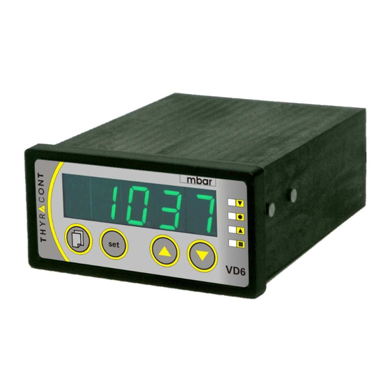
USB Anschlusskabel 2m, WUSB0002 Windows-Software VacuGraph, VGR 2.3 Produktbeschreibung Das VD6 dient zum Anzeigen und Regeln von Absolutdruck. Anschließbar sind hierzu Thyracont Vakuum-Transmitter mit Signalausgang 4-20mA. Über die USB Schnittstelle des Geräts kann der Regler vom PC aus gesteuert werden. - Seite 5 1: LED Display 2: Druckeinheit 3: LED SP1: Schaltpunkt 1 bzw. oberer Schaltpunkt 4: LED: Sollwert bei 3-Punkt-Regelung 5: LED SP2: Schaltpunkt 2 bzw. unterer Schaltpunkt 6: LED: Regelung aktiv 7: Menu-Taste 8: Set-Taste 9: Aufwärts-Taste zum Einstellen von Werten 10: Abwärts-Taste zum Einstellen von Werten 11 12 14 15...
-
Seite 6: Installation
Bestimmungsgemäße Verwendung Das VD6 dient in Verbindung mit Vakuum-Transmittern der Firma Thyracont zur Messung und Regelung von Absolutdruck. Es darf nur an geeignete und hierfür vorgesehene Komponenten angeschlossen werden. Nicht bestimmungsgemäße Verwendung Als nicht bestimmungsgemäß gilt der Einsatz zu Zwecken, die von oben genann- ten abweichen, insbesondere: der Anschluss an Geräte oder Komponenten, die laut ihrer Betriebs-... -
Seite 7: Schalttafeleinbau
Zur Schalttafelmontage sind die mitgelieferten Befestigungsspangen zu verwen- den. Das Gerät in den Schalttafelausbruch einschieben und die Spangen -wie in der Abbildung unten gezeigt- in die seitlich am VD6-Gehäuse angebrachten Befestigungsknöpfe einhaken. Zur Fixierung die Schrauben von hinten anziehen, so dass das Gerät von hinten gegen die Schalttafel geklemmt wird. -
Seite 8: Anschluss Vakuum-Transmitter
Das Gerät muss sich im ausgeschalteten Zustand befinden, wenn Vakuum-Transmitter angeschlossen werden. Nichtbeachten dieser Anweisung kann zu Schäden am Gerät füh- ren. An das Gerät kann ein Thyracont Vakuum-Transmitter für Absolutdruck ange- schlossen werden. Zulässige Typen hierfür sind: VSC43MA4 (1400 – 1 mbar) VCC200MA4 (200 – 0,1 mbar) VSP63MA4 (1000 –... -
Seite 9: Relais-Ausgänge
Messungen zu dokumentieren oder Sollwerte zu programmieren. 3.6 Relais-Ausgänge Zur externen Steuerung stehen an diesem Ausgang die Schaltfunktionen des VD6 in Form von 2 Wechsel-Relais Schaltpunkten SP1 und SP2 zur Verfügung (Darstellung in Ruhelage, stromlos, d.h. Schaltfunktion aus). Beigelegten Gegenstecker zum Verdrahten verwenden. Stecker nur in spannungsfreiem Zustand anschließen, anstecken oder... -
Seite 10: Schreiberausgang
3.7 Schreiberausgang Klinkenbuchse Analog Out, 0-1V / 0-10V, min.10kΩ AGND Am Schreiberausgang steht der gemessene Absolutdruck als analoges Span- nungssignal zur Verfügung. Der Spannungswert hängt je nach angeschlosse- nem Vakuum-Transmitter linear oder logarithmisch vom angezeigten Druck ab. Der Schreiberausgang kann dabei auf 0-1V oder 0-10V konfiguriert werden. Die Konfiguration sowie der Zusammenhang zwischen angezeigtem Druck und Ausgangsspannung sind in Abschnitt 5.3 beschrieben. -
Seite 11: Betrieb
Das Gerät befindet sich nun im Messmodus. Falls der Regler –wie in Abschnitt 5.4 beschrieben- startaktiv konfiguriert wurde (Startmodus "run"), steuert das VD6 simultan mit der Anzeige des Druck- Istwertes bereits die beiden Relais-Schaltausgänge. Ansonsten befinden sich die Relais Wechselschalter im Ruhezustand. -
Seite 12: Schaltpunkte
4.3 Schaltpunkte Das VD6 kann –wie unter Abschnitt 5.2 beschrieben- als Zwei- oder Dreipunkt- Regler konfiguriert werden. Schaltverhalten "2P" (2-Punkt-Regler) Die Relais-Schaltausgänge SP1 und SP2 werden jeweils mit Sollwert und zugehöriger Hysterese (H1 bzw. H2) eingestellt. Beide Schaltausgänge arbeiten voneinander unabhängig. - Seite 13 Zum Einstellen der Schaltpunkte von SP1 (oder SP2): Taste Menu (mehrmals) drücken, bis rechts neben dem Display die LED für SP1 (bzw. SP2) leuchtet. Der eingestellte Sollwert blinkt in der Anzeige. Mithilfe der Pfeiltasten den gewünschten Sollwert einstellen. Bestätigen mit der Set-Taste. Im Display blinkt die momentan eingestellte Hysterese.
- Seite 14 Zum Einstellen der Schaltpunkte: Taste Menu (mehrmals) drücken, bis im Display die LED "Sollwert 3-Punkt- Regelung" leuchtet. Der eingestellte Sollwert blinkt in der Anzeige. Mithilfe der Pfeiltasten den gewünschten Sollwert einstellen. Bestätigen mit der Set-Taste. Im Display blinkt die momentan eingestellte Hysterese H1 für Evakuierung.
-
Seite 15: Regelung Starten Und Stoppen
Änderungen verworfen und der ursprüngliche Zustand wieder angezeigt (Undo-Funktion). 4.4 Regelung starten und stoppen Wird im Display des VD6 der momentan gemessene Absolutdruck angezeigt (Messmodus), so kann mit der "set"-Taste die Regelung gestartet und gestoppt werden: Regelung eingeschaltet. -
Seite 16: Kommunikationsprotokoll
4.6 Kommunikationsprotokoll Wird die rückseitige Mini USB-Buchse des VD6 durch ein geeignetes Schnittstel- len-Kabel (Zubehör WUSB0002) mit einem PC verbunden, so kann z.B. mittels VacuGraph Software (Zubehör VGR) der Regler vom PC aus via Virtual-Com- Port Protokoll gesteuert werden. Die Kommunikation erfolgt gemäß Thyracont-Protokoll. Die Befehle werden in folgendem Rahmen als Zeichenfolge im ASCII-Code übertragen:... -
Seite 17: Konfiguration
Thyracont-Kommunikationsprotokolls. 5 Konfiguration Änderungen der Geräte-Konfiguration nur von geschultem Fachpersonal durchführen lassen! Um im Konfigurationsmodus Grundeinstellungen des VD6 zu ändern: Die "set"-Taste gedrückt halten wäh- rend das Gerät an die Stromversor- gung angeschlossen wird, bis die Anzeige "typ .." erscheint. -
Seite 18: Transmitter Typ
Typ9: VSP63MA4, 1000-1x10 mbar Zum Einstellen des Transmittertyps das VD6 wie unter Abschnitt 5 beschrieben in den Konfigurationsmodus schalten, so dass die Anzeige "typ .." erscheint. Der momentan eingestellte Transmittertyp wird angezeigt. Mithilfe der Pfeiltasten kann nun zwischen den verschiedenen Typen gewechselt werden. -
Seite 19: Schaltverhalten
Einstellbar sind ein gemeinsamer Sollwert und jeweils eine asymmetrische Hysterese (Schaltpunktabstand). Zum Einstellen des Schaltverhaltens das VD6 wie unter Abschnitt 5 beschrieben in den Konfigurationsmodus schalten, so dass die Anzeige "typ .." erscheint. Taste Menu (mehrmals) drücken, bis im Display die Anzeige des momentan gewählten Schaltverhaltens erscheint. -
Seite 20: Analogausgang
5.3 Analogausgang Das Analogsignal des VD6 Schreiberausgangs (siehe Abschnitt 3.6) kann auf 0-1V oder 0-10V konfiguriert werden. Einstellung 0 – 1.0 V: VD6 mit Vakuum-Transmitter Typ1 / VSC43MA4: 0 – 1 V, linear; 0,282 V entspricht 1 mbar; 1,408 V entspricht 1400 mbar VD6 mit Vakuum-Transmitter Typ3 / VSP53MA4: 0 –... - Seite 21 (Vout(V) - 5.5) p (mbar) = 10 8,5 V entspricht 1000 mbar Zum Konfigurieren des Analogausgangs das VD6 wie unter Abschnitt 5 beschrieben in den Konfigurationsmodus schalten, so dass die Anzeige "typ .." erscheint. Taste Menu (mehrmals) drücken, bis im Display "Pout" zur Konfiguration des Analogausgangs erscheint.
-
Seite 22: Startmodus
USB ist unabhängig von den hier gemachten Einstellungen in je- dem Falle möglich. Zum Ändern des Startmodus das VD6 wie unter Abschnitt 5 beschrieben in den Konfigurationsmodus schalten, so dass die Anzeige "typ .." erscheint. Taste Menu (mehrmals) drücken, bis im Display die momentan gewählte Start- Konfiguration erscheint. -
Seite 23: Wartung Und Service
Das Gerät ist wartungsfrei. Äußerliche Verschmutzungen können mit einem feuchten Tuch beseitigt werden. Sollte wider Erwarten ein Schaden an Ihrem VD6 auftreten, senden Sie das Gerät bitte mit einer Kontaminationserklärung zur Reparatur an uns. Das Gerät ist nicht zur kundenseitigen Reparatur vorgesehen! - Seite 24 man_vd6s2-de-150615...
-
Seite 25: Technische Daten
7 Technische Daten Anzeige LED 13mm; max. 4 ½ stellig Anzeigeeinheit mbar (Torr auf Anfrage) Anzeigerate 2 Hz (0,5s) Abtastrate 20 Hz (50 ms) Spannungsversorgung VD6S2230: 230 VAC, 50/60 Hz VD6S2115: 115 VAC, 50/60 Hz Leistungsaufnahme max. 3,5 W Sicherung VD6S2230: 100 mA/T VD6S2115: 200 mA/T Betriebstemperatur... -
Seite 26: Konformitätserklärung
Konformitätserklärung man_vd6s2-de-150615... - Seite 27 Content Safety Instructions ............... 28 The VD6 Display and Control Unit..........29 For Orientation ................. 29 Delivery Content ............... 29 Product Description ..............29 Installation ..................31 Notes for Installation ..............31 Panel Installation ..............32 Mains Connection..............32 Transducer Connection ............33 USB Connection ...............
-
Seite 28: Safety Instructions
Comply with all safety instructions and regulations for accident prevention Check regularly that all safety requirements are being complied with Take account of ambient conditions when installing your VD6. The protection class is IP 20, which means the unit is protected against penetration of foreign bodies. -
Seite 29: The Vd6 Display And Control Unit
USB cable 2m, WUSB0002 Windows-Software VacuGraph, VG 2.3 Product Description The VD6 is designed to display and control absolute pressure. You can connect Thyracont vacuum transducers with 4-20mA signal output. Via USB interface the instrument you can be remote controlled by a PC. - Seite 30 1: LED display 2: Pressure dimension 3: LED SP1: setpoint 1 / upper switchpoint 4: LED: setpoint (for 3-state-control) 5: LED SP2: setpoint 2 / lower switchpoint 6: LED: control on 7: Menu-key 8: Set-key 9: Up-key for value adjustment 10: Down-key for value adjustment 11 12 14 15...
-
Seite 31: Installation
Proper Use The VD6 serves exclusively to display and control absolute pressure in combina- tion with Thyracont vacuum transducers. It may only be connected to compo- nents specifically provided for such purpose. Improper Use The use for purposes not covered above is regarded as improper, in particular: the connection to components not allowed for in their operating instructions the connection to components containing touchable, voltage carrying parts. -
Seite 32: Panel Installation
For installation please use the mounting brackets which came enclosed with the VD6. Insert the VD6 in the panel and hook the brackets into the mounting knobs at the sides of the instrument as shown below. To fix the unit tighten the screws so that the VD6 is clamped against the panel. -
Seite 33: Transducer Connection
The instrument must be switched off before any transducers are connected. Not following this instruction may lead to damage of the instrument. To the VD6 Thyracont transducers for absolute pressure can be connected. Admissible types are: VSC43MA4 (1400 – 1 mbar) , VCC200MA4 (200 –... -
Seite 34: Relay Outputs
Windows-Software VacuGraph 3.6 Relay Outputs For process control the VD6 provides 2 change-over relay switching outputs SP1 and SP2 (shown in rest position, current- less, i.e. switching function off). Use enclosed counter plug for electrical connection. Connect only when power is off. -
Seite 35: Recorder Output
3.7 Recorder Output Jack Plug Analog Out, 0-1V / 0-10V,min.10kΩ AGND The recorder output provides an analog voltage signal corresponding to actual pressure. The voltage output has a linear or logarithmic characteristic depending on the connected transducer type. The recorder output can further be configured as 0-1 V or 0-10V signal. -
Seite 36: Operation
4 Operation 4.1 Startup First a transducer must be connected to the VD6 according to chapter 3.4. As soon as the mains power supply is connected, the display will show the following information: display test (all segments) firmware version selected transducer type actual pressure. -
Seite 37: Switchpoints
4.3 Switchpoints The VD6 can be configured as two- or three-state-controller as described in chapter 5.2. Switching Mode "2P" (2-state-control) The relay outputs SP1 and SP2 are each adjusted by a setpoint and a related hysteresis (H1 and H2). Both switching outputs work independently of each other. - Seite 38 In order to adjust the switchpoints SP1 (or SP2): Press the menu key (several times), until the LED for SP1 (SP2) is on. The current setpoint is flashing in the display. Adjust the setpoint by means of the "Up" and "Down" keys. Confirm with "Set"...
- Seite 39 In order to adjust the switchpoints: Press the menu key (several times), until the LED "setpoint 3-state-control" is on. The current setpoint is flashing in the display. Adjust the setpoint by means of the "Up" and "Down" keys. Confirm with "Set" key. In the display the current hysteresis H1 for evacuation is flashing.
-
Seite 40: Start Or Stop Control
If no key is pressed for 5s or if changes are quitted by the menu key, changes are discarded and the primary state is restored (undo function). 4.4 Start or Stop Control When the VD6 display shows the actual pressure reading (measurement mode), control can be started and stopped by means of the "set"-key: Control on. -
Seite 41: Communication Protocol
4.6 Communication Protocol When the Mini USB port at the back of the VD6 is connected to a PC by a suitable interface cable (accessory WUSB0002), the instrument can be remote controlled by the PC via Virtual-Com-Port protocol, e.g. using VacuGraph Software (accessory VGR). -
Seite 42: Configuration
5 Configuration Changes of the instrument configuration should be carried out only by qualified personnel! In order to change settings of the VD6 in the configuration mode: Hold the "set"-key pressed during power on of the VD6 until the dis- play shows "typ ..". -
Seite 43: Transducer Type
Typ9: VSP63MA4, 1000-1x10 mbar To select the transducer type switch the VD6 into configuration mode as described in chapter 5, so that the display shows "typ ..". The currently selected transducer type is displayed. Select the required type by means of the "Up" and "Down" keys. -
Seite 44: Switching Mode
The two switching outputs operate as relays for evacuation and venting. A common setpoint with asymmetric hysteresis is adjustable. To select the switching mode put the VD6 into configuration mode as described in chapter 5, so that the display shows "typ ..". -
Seite 45: Recorder Output
5.3 Recorder Output The analog signal of the VD6 recorder output (see chapter 3.6) can be config- ured as 0-1V or 0-10V output. Setting 0 – 1.0 V: VD6 with transducer type 1 / VSC43MA4: 0 – 1 V, linear;... - Seite 46 (mbar) = 10 8.5 V corresponds to 1000 mbar To configure the recorder output switch the VD6 into configuration mode as described in chapter 5, so that the display shows "typ ..". Press the menu key (several times) until the display shows "Pout".
-
Seite 47: Start Mode
USB independently of the settings made under this configuration point. To change the start mode switch the VD6 into configuration mode as described in chapter 5, so that the display shows "typ ..".. Press the menu key (several times) until the display shows the current start mode setting You can select between "Stop"... -
Seite 48: Maintenance And Service
The unit requires no maintenance. External dirt and soiling can be removed by a damp cloth. Should a defect or damage occur on the VD6, please return the instrument for repair, enclosing a contamination declaration. The unit is not planned for customer repair! - Seite 49 man_vd6s2-de-150615...
-
Seite 50: Technical Data
7 Technical Data Display LED 13mm; max. 4 ½ digits display unit mbar (Torr on request) Display Refresh Rate 2 Hz (0,5s) Scanning Rate 20 Hz (50 ms) Voltage Supply VD6S2230: 230 VAC, 50/60 Hz VD6S2115: 115 VAC, 50/60 Hz Power Consumption max. -
Seite 51: Declaration Of Conformity
Declaration of Conformity man_vd6s2-de-150615... - Seite 52 man_vd6s2-de-150615...