
Verwandte Anleitungen für Torqeedo DEEP BLUE 80i 1800


Inhaltszusammenfassung für Torqeedo DEEP BLUE 80i 1800
- Seite 1 DEEP BLUE Inboard motor system Translation of the original operating instructions English Deutsch...
- Seite 2 Foreword Foreword Dear Customer, We are delighted that you have chosen our motor. Your Torqeedo DEEP BLUE sys- tem delivers cutting-edge drive technology and efficiency. It has been designed and manufactured with the utmost care and with a special fo- cus on convenience, user-friendliness and safety, and has been extensively tested before delivery.
-
Seite 3: Inhaltsverzeichnis
Contents Contents Introduction............... 6.2.3 Drive................. 24 1.1 General information on the instructions......6.2.4 Component selection..........27 1.2 Explanation of symbols............6.2.5 Energy flow..............28 1.3 Layout of the safety information........6.2.6 Navigation..............29 1.4 About this operating manual..........6.2.7 Settings................31 Equipment and controls........... - Seite 4 Contents Troubleshooting..............51 10 General conditions of warranty........53 10.1 Warranty and liability.............. 53 10.2 Capacity guarantee for high-voltage batteries..... 53 10.3 Scope of warranty..............53 10.4 Warranty process..............54 11 Disposal and environment..........55 11.1 Disposal of waste electrical and electronic equip- ment....................
-
Seite 5: Introduction
Introduction Introduction General information on the instructions Explanation of symbols These instructions describe all major functions and activities of the You will find the following symbols, warnings, or mandatory signs in the instructions DEEP BLUE system. for the DEEP BLUE system. This includes: Provision of knowledge about structure, functioning, and characteristics of the DEEP BLUE system. -
Seite 6: Layout Of The Safety Information
Introduction Layout of the safety information 1. Action step 2. Action step In these instructions, safety information is presented using standardised represen- tation and symbols. Comply with the relevant information. The hazard classes ex- The result of an instruction is presented as follows: plained are used according to the likelihood of occurrence and the severity of the consequences. -
Seite 7: Equipment And Controls
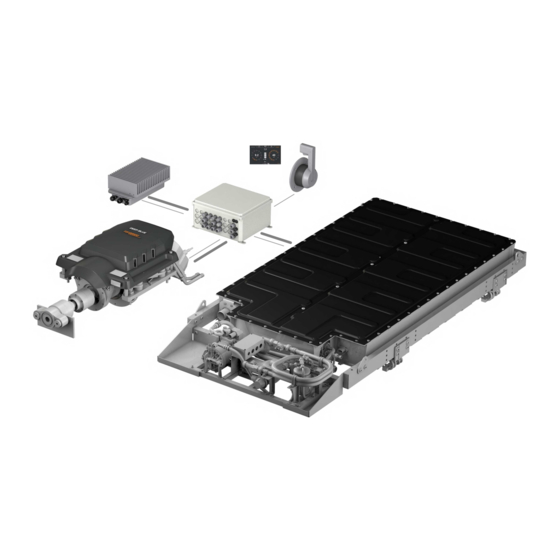
Equipment and controls Equipment and controls Overview of controls and components Overview of components Overview of controls Fig. 1: Controls Fig. 2: Components for Deep Blue 40i/80i System display, touchscreen System control Electronic accelerator lever Shore Power Distribution Emergency Stop Switch System management unit for system integration and connection of the DEEP BLUE components Key switch with key... - Seite 8 Equipment and controls Controls depending on remote throttle equipment Motor with cooling Inboard motor Fig. 3: On/Off switch Fig. 4: Emergency Off switch Fig. 5: Key switch Fig. 8: Inboard motor The inboard motor has been developed for operation as a direct shaft drive. The inboard motor is equipped with a shaft coupling and a thrust bearing.
- Seite 9 Equipment and controls High-voltage battery with cooling Cooling CA UTI O N ! Damage to the high-voltage battery from stepping on or placing objects on This can result in malfunctioning or material damage. Never step on the high-voltage battery. Never use the high-voltage battery as a support surface or lean on it. Do not place any objects on the high-voltage battery.
- Seite 10 Equipment and controls System Management Unit The high-voltage batteries of the DEEP BLUE system are charged by means of one or more AC chargers. The AC chargers convert the AC voltage of the shore supply into high-voltage direct current (DC) electricity for charging the high-voltage battery. The electrical connections are made in a separate switch box (Shore Power Distribu- tion).
-
Seite 11: Circuit Breaker
If currents greater than 3 A are permanently required for the on-board power sup- ply, then Torqeedo recommends the installation of an additional 12 V supply. This prevents the 12 V battery from becoming fully discharged, which would prevent the DEEP BLUE system from being restarted. - Seite 12 Equipment and controls Remote throttle Four different variants are available for the DEEP BLUE system: Fig. 16: Sail remote throttle lever with side mounting Fig. 17: Remote throttle lever with side mounting Fig. 18: Remote throttle lever with top mounting Fig.
-
Seite 13: Technical Data
Technical data Technical data Weight of DEEP BLUE system components Model DEEP BLUE 80 DEEP BLUE 40 - 1400/1800 - 1400/1800 Weight Maximum shaft power 62.8 kW/57.8 kW 25 kW 30.5 kWh BMW i3 high-voltage bat- 285 kg tery, with cooling and mounting frame Continuous shaft power 50 kW 25 kW... -
Seite 14: Safety
Failure to comply with these instructions can result in personal injury or property damage. Torqeedo accepts no liability for damage caused by actions which are Emergency Stop Stops the propeller immediately, and switches off the contrary to these instructions. -
Seite 15: Intended Use
Safety 4.2.2 Intended use Amongst others, the following are deemed to be unintended use: The DEEP BLUE system must be installed and operated in combination with the Operation of the propeller outside the water, even for a short period. following components: Underwater use of the DEEP BLUE system. -
Seite 16: Before Use
Safety 4.2.4 Before use W AR N IN G ! Danger to life from a boat which is not manoeuvrable! This can result in severe physical injuries or death. Before starting a trip, inform yourself of the intended travel area, and take note of the predicted weather and water conditions. -
Seite 17: General Safety Information
Do not use the DEEP BLUE system if the batteries are damaged; inform Always attach the lanyard to the skipper's wrist or his life jacket. Torqeedo Service. WARNIN G! The DEEP BLUE System has a venting opening on the casing in the unlikely event that a cell degases. - Seite 18 Safety W AR N IN G ! WARNIN G! Danger to life from a boat which is not manoeuvrable! Danger of cutting by the propeller. This can result in severe physical injuries or death. Moderate or severe physical injuries may result. Before starting a trip, inform yourself of the intended travel area, and take Keep away from the propeller.
-
Seite 19: Commissioning/Decommissioning
Commissioning/decommissioning Commissioning/decommissioning Torqeedo Service or an authorised Service Partner carries out the commissioning and decommissioning of the DEEP BLUE system. page 19 / 117... -
Seite 20: Operation
Operation Operation W AR N IN G ! Danger to life from a boat which is not manoeuvrable! This can result in severe physical injuries or death. Before starting a trip, inform yourself of the intended travel area, and take note of the predicted weather and water conditions. -
Seite 21: System Display
Operation System display The system display features a convenient and safe option for controlling the DEEP BLUE system, and for monitoring each individual component. The system display is a touch- screen. Access standby and brightness setting Control for selecting the screens Access main menu Close the pop-up window Fig. -
Seite 22: Use Of The Touchscreen Display
Operation 6.2.1 Use of the touchscreen display AD VIC E The touchscreen display can be operated using your fingers, special gloves, or a touchscreen stylus. Before a trip, ensure that the touchscreen can be operated correctly. For operating the touchscreen display, the following options are available: Select screens, buttons, or control elements by touching them Navigate between screens by swiping with two fingers or by turning the rotary knob... -
Seite 23: Main Menu
Operation 6.2.2 Main menu Drive screen Information about individual components Energy flow Service Navigation Settings Fig. 24: Main menu If no screen is selected, then after eight seconds the screen changes automatically to the Drive screen. To return to the Main menu, touch the Main Menu button at the bottom right of the screen. -
Seite 24: Drive
Operation 6.2.3 Drive All information required for normal travel mode is presented in a straightforward manner on the Drive screen. Speed over ground (shown in red if there is no valid GPS position) Remaining run time (if a GPS signal is available, the remaining range at the current speed is dis- played) State of charge of high-voltage batteries Rotational speed of shaft... - Seite 25 Operation Info area The Info area in the top part of the Drive menu contains current information on the remaining run time, rotational speed, and distance measurement. Open the Info area by touching it or swiping downwards. Close the Info area by swiping upwards.
-
Seite 26: Error Messages And Warnings
Error messages and warnings are visible only on the Drive screen. Depending on the current software version, warnings and error messages are displayed as an error code or as plain text. Torqeedo makes every effort to increase the conve- nience with each update. In the event of uncertainty, please contact Torqeedo Service. -
Seite 27: Component Selection
Operation 6.2.4 Component selection The Component Selection screen displays the operating parameters of all system components. This screen may vary depending on the components installed. The following image is an example. Present motor power Starter battery voltage Present output of AC charger units Present energy content of the high-voltage batteries Fig. -
Seite 28: Energy Flow
Operation 6.2.5 Energy flow The visual presentation of the energy flows between the system components makes it possible to obtain a rapid overview of the system’s operation. Green arrows mean that energy is being supplied to the system. Orange arrows mean that energy is being consumed. Power value: current power being transferred Direction of flow Green: Energy is being input... -
Seite 29: Navigation
Operation 6.2.6 Navigation W A RNI NG! Danger to life from overestimating the remaining range. This can result in severe physical injuries or death. Before starting a trip, make yourself familiar with the travel area, because the range displayed on the on-board computer does not take wind, current, and direction of travel into account. - Seite 30 Operation This function provides assistance for simple navigation in familiar waters. Distance from destination Travel time to destination at present speed SOC display: Estimated energy requirement to destination Compass with display of direction to start and destination Remaining range State of charge Current coordinates SOC display: Estimated energy requirement to return to start Distance from start...
-
Seite 31: Settings
Operation 6.2.7 Settings The Settings screen can be used to configure system functions, such as display modes or operating parameters. Selection of Cooling Policy Selection of brightness Select units of measure Select charger unit Select Remote Service Select information Fig. 33: Settings page 31 / 117... - Seite 32 The Remote Service tab can switch Remote Service on and off, carry out connection tests, and display the connection status. You will find further information in Remote Service. The Cooling Policy tab is used to set the temperature level from which the cooling water pumps start automatically. For internal purposes - Torqeedo Service. page 32 / 117...
-
Seite 33: Remote Service
Remote Service To commission the Remote Service maintenance function, contact Torqeedo Service. A prerequisite for use is for the user to establish an internet connection. If no individual WLAN connection was configured during installation, then an optionally installed WLAN router searches for a WLAN whose SSID is "tqr" and password is "geheim1A". In order to establish an Internet connection, a smartphone, for example, can be used to create a hotspot which uses the abovementioned data. - Seite 34 The green/red buttons display the status of the respective request. In order to ensure that the connection is permanently established, the request must be re- peated. In order to reduce the use of data volumes, Torqeedo does not use an automatically permanent request.
-
Seite 35: Remote Throttle Display
Operation Remote throttle display In addition, the remote throttle display is used for ensuring operational readiness during emergency operation and/or if the touchscreen display fails. If the system is connected to the shore-based power supply while switched off, then the charge state is displayed here. -
Seite 36: Emergency Mode
Operation Calibration Maximum reverse position AD VIC E 1. Move the lever, or both levers in the case of the double remote throttle If the Sail remote throttle with side mounting or the remote throttle with side with top mounting, to the maximum mounting is installed other than as intended (see label on the remote throttle), then this must be recalibrated manually. -
Seite 37: Emergency Stop
Operation In emergency mode, the system status of the drive is monitored by means of the An Emergency Off Switch which has been pushed down can be returned to coloured LEDs on the remote throttle lever. It is not possible to charge the system in its original position by pulling it out. -
Seite 38: Travel Mode
Operation Travel mode Position of the key switch for the throttle lever with side mounting, top mounting, and double throttle lever with top mounting Securing the Emergency Stop Switch throttle lever with side mounting Key in position 1 System is switched off. Key in position 2 System is switched on and ready to start. -
Seite 39: Starting A Trip
Operation 6.5.1 Starting a trip Starting motor using the Sail throttle lever with side mounting AD VIC E AD VICE During breaks in a trip, if there are swimmers near the boat: The system can be started only if the Emergency Stop has not been actuated. Ensure that the system is switched off, in order to prevent unintentional opera- tion of the remote throttle. -
Seite 40: Motion Forward/Reverse
Operation 6.5.2 Motion forward/reverse 55° 55° 55° 55° 55° 55° 55° 55° Fig. 42: Operating the remote throttle during Fig. 43: Operating the remote throttle during Fig. 44: Operating the remote throttle during Fig. 45: Operating the remote throttle during forwards/backwards motion forwards/backwards motion forwards/backwards motion... -
Seite 41: End Trip
Operation Charging the high-voltage batteries 6.5.3 End trip Sail accelerator lever with side mounting DANGER ! Move the lever back to the neutral position and press the On/Off switch in order to switch off the complete system. Danger of fire and burns from overheating or from hot surfaces on the components. - Seite 42 Operation 2. To end the charging process, pull the charger plug out of the socket. AD VIC E Although the high-voltage batteries of the DEEP BLUE system are protected from deep discharging, a certain self-discharge is unavoidable. In order to prevent damage to the high-voltage batteries, comply with the fol- lowing instructions: Top-up the charge of the high-voltage batteries after every trip.
-
Seite 43: Towing The Boat
Towing the boat Towing the boat CA UTI O N ! Damage to drive components from ground contact when towing. Material damage can result. While in motion, ensure that there is no danger of the propeller making con- tact with the ground. AD VIC E While the boat is ashore, set Cooling Policy to Late. -
Seite 44: Care And Service
If the batteries or other components show signs of mechanical damage, stop tected from becoming deeply discharged. Because batteries are subject to self-dis- using the DEEP BLUE system. Contact Torqeedo Service or an authorised ser- charge, a damaging deep discharging is nevertheless possible; this can result in the vice partner. -
Seite 45: Maintenance Intervals
Check flow Connections/hoses Check for leaks Venting of high-voltage battery (op- Check attachment tional) Check draining openings Check by the customer (O) or by Torqeedo technician (X) Overall system Activity 1000 h/annually Special intervals All system components Check attachment Motor and battery... - Seite 46 Care and service Inboard Motor Activity 1000 h/annually Special intervals Temperature sensor on gearbox Check for corrosion Check for tight fit Cooling system Check hoses and hose connections/clips Replace cooling water pump O | every 1000 h Drive train Visual, functional inspection i3 battery 30.5 kWh Activity 1000 h/annually...
-
Seite 47: Replacement Parts
General plugs and connections Visual inspection and checking attachment Electrical test Whichever is earlier 8.3.1 Replacement parts ADV I C E For information on replacement parts and their installation, contact Torqeedo Service or an authorised Service Partner. page 47 / 117... -
Seite 48: Storage
Care and service Storage 1. Close all cooling circuit water inlets. 2. Prepare approx. 10 to 20 litres of water/glycol mixture (mix ratio: 1:1) in a con- CA UTI O N ! tainer. Danger of burns from hot surfaces or liquids. 3. - Seite 49 4. Recharge the high-voltage battery if the charge state is less than 20 %. 5. Check whether there are warnings or error messages in the system. If there is a warning or error message, contact a certified Torqeedo dealer or Torqeedo Service.
-
Seite 50: Nameplate And Serial Number
Every DEEP BLUE system has an individual system serial number which is relevant for guarantee purposes. At Torqeedo, all components of the systems are managed un- der this number. This system serial number is applied to the side of the System Man- agement Unit. -
Seite 51: Troubleshooting
Troubleshooting Troubleshooting Error Cause Checking/correction System display does not switch on after turning Main switch is off Check the boat's main switch, and switch it on if necessary. the key switch or inserting the charger plug. 1. Check the charge state of the 12 V battery. If the charge state is low, switch off all loads not forming part of the electrical drive system;... - Seite 52 Contact Torqeedo Service or an authorised Service Partner. the electrical drive system. For any error which is not listed, and for any error which cannot be corrected through the measures described above, contact Torqeedo Service or an authorised Service Part- ner.
-
Seite 53: General Conditions Of Warranty
Torqeedo decides whether defective parts are repaired or replaced. Distributors Force majeure or other factors outside the field of influence of Torqeedo and dealers who carry out repair work on Torqeedo motors have no power to make Effect of open flame or great heat legally binding statements on behalf of Torqeedo. -
Seite 54: 10.4 Warranty Process
The safety, operating, and care information in the instructions were not followed. In the event of a claim, please contact Torqeedo Service. This team will provide Prescribed maintenance intervals were not complied with and documented. you with a return ID number. -
Seite 55: Disposal And Environment
In addition, valuable raw materials are lost in this way. Please therefore direct your waste equipment for separate collection in an environ- mentally friendly way; to do so, contact your Torqeedo Service team or boat builder. For customers in other countries The DEEP BLUE system is subject to European directive 2012/19/EUregarding waste electrical and electronic equipment. -
Seite 56: Ec Declaration Of Conformity
Torqeedo GmbH Address: Friedrichshafener Strasse 4a, 82205 Gilching, Germany For systems consisting of one of the products listed below 3305-00-Deep Blue 80i 1800 V1.4 3303-00-Deep Blue 80i 1800 V1.4 3307-00-Deep Blue 40i 1800 V1.4 3304-00-Deep Blue 40i 1400 V1.4 in combination with 4105-00 –... - Seite 57 This statement applies to all examples which are manufactured as per the corresponding production drawings, which are a component of the technical documentation. This declaration is made for and on behalf of the manufacturer Name: Torqeedo GmbH Address: Friedrichshafener Strasse 4a...
-
Seite 58: Copyright
Contraventions create an obligation to compensate for damages. The right to further claims is reserved. Torqeedo reserves the right to modify this document without advance notification. Torqeedo has taken significant efforts to ensure that these instructions are free from errors and omissions. page 58 / 117... - Seite 59 Torqeedo Service Center Germany, Austria, Switzerland North America Torqeedo GmbH Torqeedo Inc. - Service Centre - 171 Erick Street, Unit D- 2 Friedrichshafener Strasse 4a Crystal Lake, IL 60014 82205 Gilching Germany service@torqeedo.com service_usa@torqeedo.com T +49 - 8153 - 92 15 - 126...
- Seite 60 DEEP BLUE Innenbordmotor System Originalbetriebsanleitung English Deutsch...
- Seite 61 Bemerkungen zum Entwurf und der Benutzung unserer Produkte haben, wür- den wir uns freuen, wenn Sie uns darüber informieren. Generell können Sie sich mit allen Ihren Fragen zu Torqeedo Produkten jederzeit gerne an uns wenden. Die Kontakte hierzu finden Sie auf der Rückseite. Wir wün- schen Ihnen viel Freude mit diesem Produkt.
- Seite 62 Inhaltsverzeichnis Inhaltsverzeichnis Einleitung................64 6.2.3 Antrieb................83 1.1 Allgemeines zur Anleitung............ 64 6.2.4 Komponentenauswahl..........86 1.2 Zeichenerklärung............... 64 6.2.5 Energiefluss..............87 1.3 Aufbau der Sicherheitshinweise.......... 65 6.2.6 Navigation..............88 1.4 Zu dieser Betriebsanleitung..........65 6.2.7 Einstellungen..............89 Ausstattung und Bedienelemente........66 6.3 Ferngas-Display................
- Seite 63 Inhaltsverzeichnis Fehlersuche................ 109 10 Allgemeine Garantiebedingungen........111 10.1 Gewährleistung und Haftung..........111 10.2 Kapazitätsgarantie für Hochvolt-Batterien...... 111 10.3 Garantieumfang................. 111 10.4 Garantieprozess................112 11 Entsorgung und Umwelt..........113 11.1 Entsorgung von Elektro- und Elektronik-Altgeräten... 113 12 EG-Konformitätserklärung..........114 13 Urheberrecht..............116 Seite 63 / 117...
-
Seite 64: Einleitung
Achten Sie darauf, immer eine aktuelle Version der Anleitung zu verwenden. Die ak- belasten tuelle Version der Anleitung kann im Internet auf der Website www.torqeedo.com unter dem Reiter „Service Center“ heruntergeladen werden. Softwareaktualisierun- gen können zu Änderungen in der Anleitung führen. -
Seite 65: Aufbau Der Sicherheitshinweise
Einleitung Aufbau der Sicherheitshinweise Zu dieser Betriebsanleitung Sicherheitshinweise sind in dieser Anleitung mit standardisierter Darstellung und Handlungsanweisungen Symbolen wiedergegeben. Beachten Sie die jeweiligen Hinweise. Abhängig von der Auszuführende Schritte sind als nummerierte Liste dargestellt. Die Reihenfolge der Wahrscheinlichkeit des Eintretens und der Schwere der Folge werden die erklärten Schritte ist einzuhalten. -
Seite 66: Ausstattung Und Bedienelemente
Ausstattung und Bedienelemente Ausstattung und Bedienelemente Übersicht Bedienelemente und Komponenten Übersicht Komponenten Übersicht Bedienelemente Abb. 48: Bedienelemente Abb. 49: Komponenten Deep Blue 40i/80i System-Display, Touchscreen Systemsteuerung Elektronischer Gashebel Shore Power Distribution Not-Stopp-Schalter System Management Unit zur Systemintegration und Verbindung der DEEP BLUE Komponenten Schlüsselschalter mit Schlüssel Innenborder mit elektrischem Motor und Leistungselektronik... -
Seite 67: Bedienelemente Je Nach Ferngasausstattung
Ausstattung und Bedienelemente Bedienelemente je nach Ferngasausstattung Motor mit Kühlung Innenbordmotor Abb. 50: An/Aus-Schalter Abb. 51: Not-Aus-Schalter Abb. 52: Schlüsselschalter Abb. 55: Innenbordmotor Der Innenbordmotor ist für den Betrieb als direkter Wellenantrieb entworfen. Der Innenbordmotor verfügt über eine Wellenkupplung und ein Staudrucklager. Durch die Kopplung an die Welle über eine Aquadrive CV10- oder CV15-Gleich- laufgelenkwelle werden Motorvibrationen absorbiert. -
Seite 68: Hochvolt-Batterie Mit Kühlung
Ausstattung und Bedienelemente Hochvolt-Batterie mit Kühlung Kühlung VOR SIC HT! Beschädigung der Hochvolt-Batterie durch Betreten oder Ablegen von Ge- genständen! Fehlfunktionen oder Sachschäden können die Folge sein. Hochvolt-Batterie niemals betreten. Niemals auf der Hochvolt-Batterie abstützen. Keine Gegenstände auf der Hochvolt-Batterie ablegen. Abb. - Seite 69 Ausstattung und Bedienelemente System Management Unit Die Hochvolt-Batterien des DEEP BLUE Systems werden über ein oder mehrere Wechselstrom-Ladegeräte aufgeladen. Die Wechselstrom-Ladegeräte wandeln den Wechselstrom der Landstromversorgung in Hochvolt-Gleichstrom zum Laden der Hochvolt-Batterie um. Die elektrische Verschaltung erfolgt in einem separaten Schaltkasten (Shore Power Distribution).
- Seite 70 DEEP BLUE System nicht mehr einschalten lässt. Falls dauerhaft Ströme von mehr als 3 A für das Bordnetz benötigt werden, empfiehlt Torqeedo die Installation einer zusätzlichen 12 V-Versorgung. So wird verhindert, dass die 12 V-Batterie vollständig entladen wird und sich das DEEP BLUE System nicht mehr einschalten lässt.
-
Seite 71: Widerstand Des Ferngashebels Einstellen
Ausstattung und Bedienelemente Ferngas Für das DEEP BLUE System stehen vier verschiedene Varianten zur Auswahl: Abb. 63: Ferngashebel Sail – Seitenmontage Abb. 64: Ferngashebel – Seitenmontage Abb. 65: Ferngashebel – Topmontage Abb. 66: Doppel-Ferngashebel – Topmontage Madenschraube Widerstand des Ferngashebels einstellen 1. -
Seite 72: Technische Daten
Technische Daten Technische Daten Gewicht DEEP BLUE Systemkomponenten Modell DEEP BLUE 80 DEEP BLUE 40 - 1400/1800 - 1400/1800 Gewicht Maximale Wellenleistung 62,8 kW/57,8 kW 25 kW Hochvolt-Batterie 30.5 kWh BMW i3, 285 kg mit Kühlung und Montagerahmen Dauer-Wellenleistung 50 kW 25 kW Pro Ladegerät 3 kW 10 kg... -
Seite 73: Sicherheit
Fehlende Berücksichtigung dieser Hinweise kann Personen- oder Sachschäden zur Folge haben. Torqeedo übernimmt keine Haftung für Schäden, die durch Not-Stopp Bewirkt einen sofortigen Stillstand der Propeller und Handlungen entstanden sind, die im Widerspruch zu dieser Anleitung stehen. -
Seite 74: Bestimmungsgemäße Verwendung
Sicherheit 4.2.2 Bestimmungsgemäße Verwendung Unter anderem gilt als nicht bestimmungsgemäß: Das DEEP BLUE System muss in Verbindung mit folgenden Komponenten in- Der Betrieb des Propellers auch kurzfristig außerhalb des Wassers. stalliert und betrieben werden: Ein Unterwassereinsatz des DEEP BLUE Systems. Hochvolt-Batterie/gekühlt Der Betrieb in Gewässern, die mit Chemikalien versetzt werden. -
Seite 75: Vor Dem Gebrauch
Sicherheit 4.2.4 Vor dem Gebrauch Prüfen Sie den Zustand und alle Funktionen des DEEP BLUE Systems (inklusive Not-Stopp) vor jeder Fahrt bei geringer Leistung, siehe Kapitel 8.3, "Service-In- W AR NUN G! tervalle". Lebensgefahr durch nicht manövrierfähiges Boot! Machen Sie sich mit allen Bedienelementen des DEEP BLUE Systems vertraut. Sie Schwere Gesundheitsschäden oder Tod können die Folge sein. -
Seite 76: Allgemeine Sicherheitshinweise
Benutzen Sie das DEEP BLUE System bei Beschädigungen an der Batterie Befestigen Sie die Abzugsleine immer am Handgelenk oder der Rettungs- nicht und informieren Sie den Torqeedo Service. weste des Bootsführers. Das DEEP BLUE System hat eine Venting-Öffnung am Gehäuse für den un- wahrscheinlichen Fall des Entgasens einer Zelle. - Seite 77 Sicherheit W AR NUN G! WA RNUN G! Mechanische Gefährdung durch rotierende Bauteile! Verletzungsgefahr durch Propeller! Schwere Körperverletzungen oder Tod können die Folge sein. Mittlere oder schwere Körperverletzungen können die Folge sein. Tragen Sie keine weite Kleidung oder Schmuck in der Nähe der Antriebswelle Schalten Sie bei Arbeiten am Propeller das System stets über den Haupt- oder des Propellers.
-
Seite 78: Inbetriebnahme/Außerbetriebnahme
Inbetriebnahme/Außerbetriebnahme Inbetriebnahme/Außerbetriebnahme Die Inbetrieb- und Außerbetriebnahme des DEEP BLUE Systems erfolgt durch den Torqeedo Service oder einen autorisierten Servicepartner. Seite 78 / 117... -
Seite 79: Betrieb
Betrieb Betrieb W AR NUN G! Lebensgefahr durch nicht manövrierfähiges Boot! Schwere Gesundheitsschäden oder Tod können die Folge sein. Informieren Sie sich vor Fahrtbeginn über das vorgesehene Fahrtgebiet und beachten Sie die vorhergesagten Wetter- und Seegangsverhältnisse. Halten Sie abhängig von der Größe des Bootes die typische Sicherheitsaus- rüstung bereit (Anker, Paddel, Kommunikationsmittel, ggf. -
Seite 80: System-Display
Betrieb System-Display Das System-Display bietet eine komfortable und sichere Möglichkeit, das DEEP BLUE System zu kontrollieren und jede einzelne Komponente zu überwachen. Bei dem System-Display handelt es sich um ein Touchscreen-Display. Standby und Helligkeitseinstellung aufrufen Bedienelement zur Auswahl der Bildschirme Hauptmenü... -
Seite 81: Bedienung Des Touchscreen-Displays
Betrieb 6.2.1 Bedienung des Touchscreen-Displays HIN W EI S Die Bedienung des Touchscreen-Displays ist mit Fingern, speziellen Handschu- hen oder einem Touchscreen-Stift möglich. Stellen Sie die Bedienbarkeit vor der Fahrt sicher. Um das Touchscreen-Display zu bedienen, haben Sie folgende Möglichkeiten: Auswählen von Bildschirmen, Schaltflächen oder Kontrollelementen durch Antip- Navigieren zwischen den Bildschirmen durch Wischen mit zwei Fingern oder Dre- hen des Drehrads... -
Seite 82: Hauptmenü
Betrieb 6.2.2 Hauptmenü Antriebsbildschirm Informationen zu einzelnen Komponenten Energiefluss Service Navigation Einstellungen Abb. 71: Hauptmenü Falls kein Bildschirm ausgewählt wird, wechselt der Bildschirm nach acht Sekunden automatisch zum Antriebsbildschirm. Um wieder zum Hauptmenü zu gelangen, tippen Sie auf die Hauptmenü-Schaltfläche unten rechts im Bildschirm. Abb. -
Seite 83: Antrieb
Betrieb 6.2.3 Antrieb Auf dem Antriebsbildschirm werden alle für den normalen Fahrbetrieb notwendigen Informationen in übersichtlicher Form dargestellt. Geschwindigkeit über Grund (wird ohne gültige GPS-Position in rot darge- stellt) Verbleibende Restlaufzeit (wenn ein GPS-Signal verfügbar ist, wird die verbleibende Reichweite bei ak- tueller Geschwindigkeit angezeigt) Ladestand der Hochvolt-Batterien Wellendrehzahl... -
Seite 84: Info-Bereich
Betrieb Info-Bereich Der Info-Bereich im oberen Bereich des Antriebsmenüs enthält aktuelle Informatio- nen zur verbleibenden Restlaufzeit, Drehzahl und Entfernungsmessung. Öffnen Sie den Info-Bereich, indem Sie ihn antippen oder nach unten wischen. Schließen Sie den Info-Bereich, indem Sie nach oben wischen. Die Werte werden kombiniert angezeigt. -
Seite 85: Fehlermeldungen Und Warnungen
Fehlermeldungen und Warnungen sind nur im Antriebsbildschirm sichtbar. Warnungen und Fehlermeldungen werden je nach aktueller Softwareversion als Fehlercode oder als Klartext angezeigt. Torqeedo ist bemüht, den Komfort mit jedem Update weiter zu steigern. Kontaktieren Sie bei Unklarheiten den Torqeedo Service. -
Seite 86: Komponentenauswahl
Betrieb 6.2.4 Komponentenauswahl Auf dem Komponentenauswahl-Bildschirm werden die Betriebsparameter aller Systemkomponenten angezeigt. Je nachdem, welche Komponenten verbaut sind, unterscheidet sich dieser Bildschirm. Die folgende Grafik ist beispielhaft. Momentane Motorleistung Spannung der Starterbatterie Aktuelle Leistung der Wechselstrom-Ladegeräte Aktueller Energieinhalt der Hochvoltbatterien Abb. -
Seite 87: Energiefluss
Betrieb 6.2.5 Energiefluss Die visuelle Darstellung der Energieflüsse zwischen den Systemkomponenten erlaubt es, einen schnellen Überblick über den Betrieb des Systems zu bekommen. Grüne Pfeile bedeuten, dass Energie in das System eingebracht wird. Orange Pfeile bedeuten, dass Energie verbraucht wird. Leistungswert: aktuelle übertragene Leistung Flussrichtung Grün: Energie-Einspeisung. -
Seite 88: Navigation
Betrieb 6.2.6 Navigation WA RNUNG! Lebensgefahr durch Überschätzung der verbleibenden Reichweite! Schwere Gesundheitsschäden oder Tod können die Folge sein. Machen Sie sich vor Fahrtbeginn mit dem Fahrtgebiet vertraut, da die im Bordcomputer angezeigte Reichweite Wind, Strömung und Fahrtrichtung nicht berücksichtigt. Planen Sie ausreichend Puffer für die benötigte Reichweite ein. -
Seite 89: Einstellungen
Betrieb 6.2.7 Einstellungen Über den Bildschirm Einstellungen können Systemfunktionen, wie z. B. Anzeigemodi oder Betriebsparameter, konfiguriert werden. Auswahl Cooling Policy Auswahl Helligkeit Auswahl Maßeinheiten Auswahl Ladegerät Auswahl Remote Service Auswahl Info Abb. 80: Einstellungen Seite 89 / 117... - Seite 90 Über den Reiter Remote Service kann der Remote Service ein- und ausgeschaltet, Verbindungstests durchgeführt und der Verbin- dungsstatus angezeigt werden. Weitere Informationen finden Sie unter Remote Service. Über den Reiter Cooling Policy wird eingestellt, ab welchem Temperaturniveau die Kühlwasserpumpen automatisch starten. Für interne Zwecke - Torqeedo Service. Seite 90 / 117...
- Seite 91 Remote Service Für die Inbetriebnahme der Fernwartungsfunktion Remote Service, kontaktieren Sie den Torqeedo Service. Voraussetzung für die Nutzung ist die Herstellung einer Internet- verbindung durch den Benutzer. Sofern bei der Installation keine individuelle WLAN-Verbindung eingerichtet wurde, sucht ein optional eingebauter WLAN-Router nach einem WLAN mit SSID "tqr"...
- Seite 92 HIN W EI S Die Schaltflächen grün/rot zeigen den Status der jeweiligen Abfrage an. Um si- cherzustellen, dass die Verbindung dauerhaft steht, muss die Abfrage wiederholt werden. Torqeedo verzichtet zur Schonung von Datenvolumen auf eine automa- tisch dauerhafte Abfrage. Seite 92 / 117...
-
Seite 93: Ferngas-Display
Betrieb Ferngas-Display Das Ferngas-Display wird nur für die Kalibrierung des Ferngashebels verwendet. Al- le anderen Einstellungen können auch über das System-Display vorgenommen wer- den. Die Bedienung des Ferngas-Displays erfolgt durch das Drücken der jeweiligen Schaltflächen neben dem Display. Zudem dient das Ferngas-Display zur Sicherstellung der Fahrbereitschaft im Notfahr- betrieb und/oder bei Ausfall des Touchscreen-Displays. -
Seite 94: Kalibrierung
Betrieb Kalibrierung Maximale Rückwärtsposition HIN W EI S 1. Bewegen Sie den Hebel bzw. beide Hebel beim Doppel-Ferngashebel – Wird der Ferngashebel Sail – Seitenmontage oder der Ferngashebel – Seiten- Topmontage auf die maximale Rück- montage anders als vorgesehen montiert (siehe Aufkleber auf dem Ferngashe- bel), muss dieser manuell neu kalibriert werden. -
Seite 95: Not-Stopp
Betrieb Im Notbetrieb wird der Systemstatus des Antriebs über die farbigen LEDs am Fern- Ein gedrückter Not-Aus-Schalter kann durch Ziehen wieder zurück in den gashebel kontrolliert. Das Laden des Systems ist in diesem Modus nicht möglich, bis Ausgangszustand gebracht werden. die Ursachen der technischen Probleme beseitigt sind. -
Seite 96: Fahrbetrieb
Betrieb Fahrbetrieb Stellung des Schlüsselschalters Gashebel – Seitenmontage, Gashebel – Top- montage und Doppel-Gashebel – Topmontage Not-Stopp-Schalter sichern Gashebel – Seitenmontage Schlüssel in Position 1 System ist ausgeschaltet. Schlüssel in Position 2 System ist eingeschaltet und fahrbereit. Der Schlüssel kann in dieser Position nicht abgezogen werden. -
Seite 97: Fahrt Beginnen
Betrieb 6.5.1 Fahrt beginnen Motor starten mit Gashebel Sail – Seitenmontage HIN W EI S HIN WE IS Bei Fahrpausen, in denen sich schwimmende Personen in der Nähe des Bootes Das Starten des Systems ist nur möglich, wenn der Not-Stopp nicht betätigt befinden: wurde. -
Seite 98: Vorwärts-/Rückwärtsfahrt
Betrieb 6.5.2 Vorwärts-/Rückwärtsfahrt 55° 55° 55° 55° 55° 55° 55° 55° Abb. 89: Bedienung Ferngashebel bei Vor- Abb. 90: Bedienung Ferngashebel bei Vor- Abb. 91: Bedienung Ferngashebel bei Vor- Abb. 92: Bedienung Ferngashebel bei Vor- wärts-/Rückwärtsfahrt wärts-/Rückwärtsfahrt wärts-/Rückwärtsfahrt wärts-/Rückwärtsfahrt Gashebel – Topmontage, Doppel-Gashebel – Topmontage Der Ferngashebel kann maximal 55°... -
Seite 99: Fahrt Beenden
Betrieb Laden der Hochvolt-Batterien 6.5.3 Fahrt beenden Gashebel Sail – Seitenmontage GEFAH R! Bringen Sie den Hebel zurück in die Neutralstellung und drücken Sie auf den An/Aus-Schalter, um das gesamte System auszuschalten. Feuergefahr und Verbrennungsgefahr durch Überhitzung oder heiße Ober- flächen der Bauteile! Gashebel –... - Seite 100 Betrieb Über System Management | Components | Charger bzw. Battery können Sie sich Auf dem Energy Flow-Bildschirm wird ein Pfeil und die kombinierte Ladeleis- Detailwerte zum Ladevorgang anschauen. tung aller Ladegeräte angezeigt. Auf dem Display des Gashebels wird ein Steckersymbol und die Ladeleistung Der aktuelle Ladezustand kann im Antriebsbildschirm unter Time to full oder über das kleine Display jederzeit überwacht werden.
-
Seite 101: Trailern Des Bootes
Trailern des Bootes Trailern des Bootes VOR SIC HT! Beschädigung von Antriebsbauteilen durch Bodenkontakt beim Trailern! Sachschäden können die Folge sein. Stellen Sie während der Fahrt sicher, dass die Gefahr einer Bodenberührung des Propellers ausgeschlossen ist. HIN W EI S Solange das Boot an Land ist, setzen Sie Cooling Policy auf Late. -
Seite 102: Pflege Und Service
20 % entladen sind, muss das Wiederaufladen innerhalb von 48 Stunden erfol- gen. Wartungsarbeiten dürfen ausschließlich von qualifiziertem Fachpersonal durch- geführt werden. Kontaktieren Sie den Torqeedo Service oder einen autorisierten HIN WE IS Servicepartner. Stellen Sie vor Wartungs- und/oder Reinigungsarbeiten Folgendes sicher: Beachten Sie nach Fahrtende auch die Informationen aus Kapitel 8.4, "Lage-... -
Seite 103: Service-Intervalle
Filter prüfen/reinigen Pumpen Durchfluss prüfen Verbindungen/Schläuche Dichtigkeit prüfen Hochvolt-Batterie Venting (optional) Befestigung prüfen Entwässerungsöffnung prüfen Kontrolle durch Kunden (O) oder Torqeedo Techniker (X) Gesamtsystem Tätigkeit 1000 h/jährlich* Spezielle Intervalle Alle Systemkomponenten Befestigung prüfen Motor und Batterie Befestigung von Schrauben, Bolzen und Dreh- moment prüfen... - Seite 104 Pflege und Service Innenborder Tätigkeit 1000 h/jährlich* Spezielle Intervalle Temperatursensor Getriebe Auf Korrosion prüfen Auf festen Sitz prüfen Kühlsystem Schläuche und Schlauchverbindungen/Schellen prüfen Kühlwasserpumpe wechseln O | alle 1000 h Antriebsstrang Sichtprüfung, Funktionsprüfung i3-Batterie 30.5 kWh Tätigkeit 1000 h/jährlich* Spezielle Intervalle Venting Sichtprüfung Schlauch Entwässerungsschraube öffnen und ggf.
-
Seite 105: Ersatzteile
Sichtprüfung und Befestigung prüfen Elektrischer Test Je nachdem, was früher erreicht wird 8.3.1 Ersatzteile HIN W EI S Zu Informationen bezüglich Ersatzteilen und Montage von Ersatzteilen wenden Sie sich an Ihren Torqeedo Service oder einen autorisierten Servicepartner. Seite 105 / 117... -
Seite 106: Lagerung
Pflege und Service Lagerung 1. Schließen Sie die Bordeinlässe aller Seewasser-Kühlkreisläufe. 2. Stellen Sie ca. 10 - 20 Liter Wasser-Glykolgemisch (Mischungsverhältnis: 1:1) in VOR SIC HT! einem Behälter bereit. Verbrennungsgefahr durch heiße Oberflächen oder Flüssigkeiten! 3. Lösen Sie die Kühlwasser-Zuleitung innen am Bordeinlass. Leichte oder mittlere Körperverletzungen können die Folge sein. -
Seite 107: Regelmäßige Überprüfung (Alle 3 Monate)
3. Stellen Sie sicher, dass alle Kühlwasserschläuche mit den Bordeinlassventilen si- cher verbunden sind. Ist der Status nicht Balanced, setzen Sie sich mit einem zertifizierten Torqee- do-Händler oder dem Torqeedo-Service in Verbindung. 4. Öffnen Sie die Bordeinlassventile. 3. Trennen Sie das System vom Stromnetz. -
Seite 108: Typenschild Und Seriennummer
An jedem zum DEEP BLUE System gehörigen Motor ist ein geprägtes Schild zur Er- fassung der Eckdaten gemäß Maschinenrichtlinie 2006/42/EG angebracht. 000-00411 Deep Blue 80i 1800 S.Nr. 15509004A000004112 400V DC / 50kW / 1800rpm / 80kg Manufactured 2015 by Torqeedo GmbH Friedrichshafener Str. -
Seite 109: Fehlersuche
Fehlersuche Fehlersuche Fehler Ursache Prüfung/Behebung System-Display schaltet nach Drehen des Hauptschalter aus Bootsseitigen Hauptschalter prüfen, ggf. einschalten. Schlüsselschalters oder Einstecken des Ladeste- 1. Ladezustand der 12 V-Batterie prüfen. Bei niedrigem Lade- ckers nicht ein. stand alle nicht zum elektrischen Antriebssystem gehörenden Verbraucher abschalten, ggf. - Seite 110 Kontaktieren Sie den Torqeedo Service oder einen autorisierten im elektrischen Antriebssystem. Service-Partner. Bei allen nicht aufgeführten Fehlern und bei allen durch die oben beschriebenen Abstellmaßnahmen nicht behebbaren Fehlern wenden Sie sich an den Torqeedo Service oder einen autorisierten Service-Partner. HIN W EI S Erscheint im Display die Fehlermeldung "Isolationsfehler", ist die Isolierung des Hochvolt-Systems beschädigt.
-
Seite 111: Allgemeine Garantiebedingungen
Darüber hinaus übernimmt Torqeedo keine Garantie für Defekte an den Hoch- hend festgelegten Deckungszeitraumes frei von Material- und Verarbeitungsfehlern volt-Batterien und anderen Komponenten, die verursacht wurden durch: ist. Torqeedo wird den Endabnehmer von den Kosten der Beseitigung eines Mate- Unsachgemäßen Gebrauch rial- oder Verarbeitungsfehlers freihalten. Diese Freihalteverpflichtung gilt nicht für Unsachgemäße Lagerung... -
Seite 112: 10.4 Garantieprozess
Kaufgegenstand in irgendeiner Weise umgebaut, modifiziert oder mit Teilen Bitte beachten Sie bei einem eventuellen Transport von Produkten zum Torqee- oder Zubehörartikeln ausgerüstet worden ist, die nicht zu der von Torqeedo aus- do Service, dass unsachgemäßer Transport nicht durch Garantie oder Gewähr- drücklich zugelassenen bzw. -
Seite 113: Entsorgung Und Umwelt
Außerdem gehen auf diese Weise wertvolle Rohstoffe verloren. Bitte füh- ren Sie Ihre Altgeräte daher umweltverträglich einer getrennten Sammlung zu und wenden Sie sich dazu an Ihren Torqeedo Service oder an Ihren Bootsbauer. Für Kunden in anderen Ländern Das DEEP BLUE System unterliegt der europäischen Richtlinie 2012/19/EU über Elek- tro- und Elektronik-Altgeräte. -
Seite 114: Eg-Konformitätserklärung
Torqeedo GmbH Anschrift: Friedrichshafener Straße 4a, 82205 Gilching Für Systeme bestehend aus einem der nachfolgend bezeichneten Erzeugnisse 3305-00-Deep Blue 80i 1800 V1.4 3303-00-Deep Blue 80i 1800 V1.4 3307-00-Deep Blue 40i 1800 V1.4 3304-00-Deep Blue 40i 1400 V1.4 in Kombination mit 4105-00 –... -
Seite 115: Angewandte Normen
Kleinbetriebe Diese Erklärung gilt für alle Exemplare, die nach den entsprechenden Fertigungszeichnungen – die Bestandteil der technischen Dokumentation sind – hergestellt werden. Diese Erklärung wird verantwortlich für den Hersteller Name: Torqeedo GmbH Anschrift: Friedrichshafener Straße 4a 82205 Gilching, Deutschland... -
Seite 116: Urheberrecht
Zuwiderhandlungen verpflichten zu Schadensersatz. Weitere Ansprüche bleiben vor- behalten. Torqeedo behält sich das Recht vor, dieses Dokument ohne vorherige Ankündigun- gen zu ändern. Torqeedo hat erhebliche Anstrengungen unternommen, um sicher zu stellen, dass diese Anleitung frei von Fehlern und Auslassungen ist. -
Seite 117: Torqeedo Unternehmen
Torqeedo Service Center Deutschland, Österreich, Schweiz Nordamerika Torqeedo GmbH Torqeedo Inc. - Service Center - 171 Erick Street, Unit D- 2 Friedrichshafener Straße 4a Crystal Lake, IL 60014 82205 Gilching service@torqeedo.com service_usa@torqeedo.com T +49 - 8153 - 92 15 - 126...