
Verwandte Anleitungen für HYDAC AS 1000


Inhaltszusammenfassung für HYDAC AS 1000
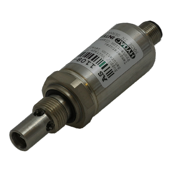
- Seite 1 Aqua Sensor AS 1000 Benutzerhandbuch (Originalanleitung) User manual (Translation of original manual)
-
Seite 2: Inhaltsverzeichnis
Aqua Sensor AS 1000 Inhalt Allgemeines ......................... 4 Sicherheitshinweise ....................4 Montage ........................4 Funktionsweise ......................5 4.1 Idealer Sättigungsgrad in Hydraulik und Schmiersystemen ......... 5 4.1.1 Arbeitsbereich AS 1008 (für mineralölbasierende Flüssigkeiten) ....6 4.1.2 Arbeitsbereich AS 1108 (für synthetische und natürliche Ester) ....6 Funktionen ........................ - Seite 3 Aqua Sensor AS 1000 Vorwort Für Sie, den Benutzer unseres Produktes, haben wir in dieser Dokumentation die wichtigsten Hinweise zum Bedienen und Warten zusammengestellt. Sie dient Ihnen dazu, das Produkt kennen zu lernen und seine bestimmungsgemäßen Einsatzmöglichkeiten optimal zu nutzen.
-
Seite 4: Allgemeines
Der elektrische Anschluss sollte von einem Fachmann nach den jeweiligen Landes- vorschriften durchgeführt werden (VDE 0100 in Deutschland). Die Sensoren der Serie AS 1000 tragen das CE - Zeichen. Eine Konformitätserklärung ist auf Anfrage erhältlich. Die EMV-Normen: EN 61000-6-1, EN 61000-6-2, EN 61000-6-3 und EN 61000-6-4 werden erfüllt. -
Seite 5: Funktionsweise
In der Variante mit 2 Schaltausgängen schalten die Schaltausgänge entsprechend dem Sättigungsgrad und den eingestellten Schaltparametern. Es besteht die Möglichkeit den AS 1000- Sensor individuell über die HYDAC Servicegeräte HMG 3010 und HMG 4000, die Condition Monitoring Unit CMU 1000 und das Schnittstellenmodul CSI-B2 an die jeweilige Applikation anzupassen. -
Seite 6: Arbeitsbereich As 1008 (Für Mineralölbasierende Flüssigkeiten)
Aqua Sensor AS 1000 Arbeitsbereich AS 1008 (für mineralölbasierende Flüssigkeiten) 4.1.1 Humidity-Temperature-Range -40 -30 -20 -10 0 10 20 30 40 50 60 70 80 90 100 110 120 130 140 150 160 170 180 190 Temperatur [°C] Die Abbildung zeigt den zulässigen Arbeitsbereich des Aqua-Sensors AS 1008. Wird der Sensor außerhalb des grau gefärbten Bereiches dauerhaft betrieben, können bleibende... -
Seite 7: Ausführung Mit 2 Schaltausgängen
Ausführung mit 2 Schaltausgängen (siehe auch Grafik S. 9) • Schalten der Schaltausgänge entsprechend dem Sättigungsgrad und den eingestellten Schaltparametern • Anpassen des AS 1000 an die jeweilige Applikation durch individuelle Benutzer- Programmierung mit dem HYDAC Servicegerät HMG 30X0 oder der Software CMWIN. 5.2.1 Ausgangsverhalten Der AS 1000-2 verfügt über 1 bzw. -
Seite 8: Einstellung Der Beiden Schaltausgänge
Aqua Sensor AS 1000 5.2.3 Einstellung der beiden Schaltausgänge Mit Hilfe des HMG 3010 oder mit der Software CMWIN haben Sie die Möglichkeit die Schaltpunkte des Sensors zu konfigurieren. Im Hauptmenü “SMART-Sensor“ wählen Sie den Menüpunkt „Sensordialog“ aus. Hier können Sie die Konfigurationen des SMART-Sensors vornehmen. -
Seite 9: Grafische Darstellung Des Ausgangsverhaltens
Aqua Sensor AS 1000 5.2.4 Grafische Darstellung des Ausgangsverhaltens Stand: 17.07.2017 Mat. Nr.: 669705 HYDAC ELECTRONIC GMBH... -
Seite 10: Elektrischer Anschluss
+U b Signal Sättigungsgrad AS 1000-C Signal Temperatur SP2, Warnung AS 1000-2 SP 1, Alarm * HSI = HYDAC Sensor Interface (HYDAC-interne Kommunikations-Schnittstelle) = (Ub – 10 V) / 20 mA [kΩ] Stand: 17.07.2017 Mat. Nr.: 669705 HYDAC ELECTRONIC GMBH... -
Seite 11: Technische Daten
Aqua Sensor AS 1000 7 Technische Daten AS 1X00-C AS 1X00-2 Eingangskenngrößen Messbereich (Sättigungsgrad) 0 .. 100 % Messbereich (Temperatur) -25 .. +100 °C Betriebsdruck - 0,5 .. 50 bar Druckfestigkeit ≤ 630 bar Mechanischer Anschluss G3/8A ISO 1179-2 Anzugsdrehmoment, empfohlen 25 Nm Medienberührende Teile... -
Seite 12: Bestellangaben
Aqua Sensor AS 1000 8 Bestellangaben 1 X 0 8 - X - 000 Medium 0 = Hydraulikflüssigkeiten auf Mineralölbasis 1 = Hydraulikflüssigkeiten auf Phosphatesterbasis Anschlussart mechanisch 0 = G 3/8A ISO 1179-2 Anschlussart elektrisch 8 = Gerätestecker M12x1, 5-pol. (ohne Kupplungsdose) -
Seite 13: Zubehör
Aqua Sensor AS 1000 10 Zubehör 10.1 Elektrisch ZBE 08 (5-pol.) Kupplungsdose M12x1, abgewinkelt Bestell-Nr.: 6006786 ZBE 08-02 (5-pol.) mit 2m Leitung Bestell-Nr.: 6006792 ZBE 08-05 (5-pol.) mit 5m Leitung Bestell-Nr.: 6006791 ZBE 08S-02 (5-pol.) mit 2m Leitung geschirmt Bestell-Nr.: 6019455 ZBE 08S-05 (5-pol.) -
Seite 14: Anzeigen
Bestell-Nr.: 909889 HMG 510-000 Anschluss an ein HMG 510 Entfernen Sie die Versorgungsleitung vom elektrischen Anschluss des AS 1000 und schrauben Sie den Anschlussadapter „ZBE 36“ oder „ZBE 46“ auf den Sensor. Verbinden Sie einen der Eingänge A oder B des HMG 510 mittels eines Sensorkabels „ZBE 30-0x“... -
Seite 15: Hmg 2500, Hmg 30X0 Und Hmg 4000
11.4 Software CMWIN Speziell entwickelte PC-Software, die mittels Kommunikationsbrücke (HMG 510, HMG 2500, HMG 30X0 oder HMG 4000) mit dem AS 1000 kommuniziert. Mit der Software können Messkurven zum PC übertragen, gespeichert, angezeigt und bearbeitet werden oder die aktuellen Messwerte dargestellt werden. - Seite 16 E-Mail: electronic@hydac.com Tel.: +49 (0)6897 509-01 Fax.: +49 (0)6897 509-1726 HYDAC Service Für Fragen zu Reparaturen steht Ihnen der HYDAC Service zur Verfügung. HYDAC SERVICE GMBH Hauptstr. 27 D-66128 Saarbrücken Germany Tel.: +49 (0)6897 509-1936 Fax: +49 (0)6897 509-1933...
- Seite 17 Aqua Sensor AS 1000 User manual (Translation of original instructions)
- Seite 18 Aqua Sensor AS 1000 Contents General ......................... 4 Safety information ....................... 4 Installation ........................4 Function ........................5 4.1 Ideal saturation level in hydraulic and lubrication systems ........5 4.1.1 Working range for AS 1008 (for mineral oil based fluids)....... 6 4.1.2...
- Seite 19 Aqua Sensor AS 1000 Preface This manual provides you, as user of our product, with key information on the operation and maintenance of the equipment. It will acquaint you with the product and assist you in obtaining maximum benefit in the applications for which it is designed.
-
Seite 20: General
The electrical connection must be carried out by a qualified electrician according to the relevant regulations of the country concerned (VDE 0100 in Germany). The sensors of the AS 1000 series carry the CE mark. A certificate of conformity is available on request. EMC standards: Compliant with EN 61000-6-1, EN 61000-6-2, EN 61000-6-3 and EN 61000-6-4. -
Seite 21: Function
You have the option of individually adapting the AS 1000 sensor to the relevant application by means of the HYDAC service devices HMG 3010 and HMG 4000, the Condition Monitoring Unit CMU 1000 and the Condition Monitorung Interface Module CSI-B2. -
Seite 22: Working Range For As 1008 (For Mineral Oil Based Fluids)
Aqua Sensor AS 1000 Working range for AS 1008 (for mineral oil based fluids) 4.1.1 -40 -25 110 125 140 155 170 185 Temperature [°C] The graph shows the permitted working range for AquaSensor AS 1008. If the sensor is operated permanently outside the range indicated in grey, lasting damage can occur to the sensor element. -
Seite 23: Version With 2 Switch Outputs
• Switching of the switch outputs according to the saturation level and the pre-set switching parameters. • The AS 1000 is adapted to the relevant application by individual user programming via the HYDAC service device HMG 30X0 or the CMWIN software. -
Seite 24: Setting Of Both Switching Outputs
Aqua Sensor AS 1000 5.2.3 Setting of both switching outputs By means of the HMG 3010 or the CMWIN software, you have the option of configuring the switch points of the sensors. Please select the menu point in the "sensor dialogue" of the main menu "SMART-Sensor". -
Seite 25: Graphical Representation Of The Output Behaviour
Aqua Sensor AS 1000 5.2.4 Graphical representation of the output behaviour Edition: 2017-07-17 Part No.: 669705 HYDAC ELECTRONIC GMBH... -
Seite 26: Electrical Connection
Signal saturation level AS 1000-C Signal temperature SP2, Warning AS 1000-2 SP 1, Alarm * HSI = HYDAC Sensor Interface (HYDAC's own communication interface) = (Ub – 10 V) / 20 mA [kΩ] Edition: 2017-07-17 Part No.: 669705 HYDAC ELECTRONIC GMBH... -
Seite 27: Technical Details
Aqua Sensor AS 1000 7 Technical Details AS 1X00-C AS 1X00-2 Input data Measuring range (saturation level) 0 .. 100 % Measuring range (temperature) -25 .. +100 °C Operating pressure -0,5 .. 50 bar Pressure resistance ≤ 630 bar Mechanical connection... -
Seite 28: Order Details
Aqua Sensor AS 1000 8 Order Details 1 X 0 8 - X - 000 Medium 0 = Mineral oil based hydraulic fluids 1 = Phosphate ester based hydraulic fluids Mechanical connection 0 = G 3/8A ISO 1179-2 Electrical connection... -
Seite 29: Accessories
Aqua Sensor AS 1000 10 Accessories 10.1 Electrical ZBE 08 (5-pole) Connector M12x1, right-angled Order no.: 6006786 ZBE 08-02 (5 pole) with 2m cable Order no.: 6006792 ZBE 08-05 (5 pole) with 5m cable Order no.: 6006791 ZBE 08S-02 (5 pole) With 2m screened cable Order no.: 6019455... -
Seite 30: Displays
Order No.: 909889 HMG 510-000 Connecting to a HMG 510 Remove the supply cable from the electrical connection of the AS 1000 and screw the connection adapter "ZBE 36" or „ZBE 46“ onto the sensor. Connect one of the inputs A or B of the HMG 510 to the output of the "ZBE 36"... -
Seite 31: Hmg 2500, Hmg 30X0 Und Hmg 4000
HMG). Connecting to an HMG 2500, HMG 30X0 or HMG 4000 Remove the supply cable from the electrical connection of the AS 1000 and screw the connection adapter "ZBE 36" or „ZBE 46“ onto the sensor. - Seite 32 Germany Web: www.hydac.com E-Mail: electronic@hydac.com Tel.: +49 (0)6897 509-01 Fax: +49-(0)6897-509-1726 HYDAC Service For enquiries regarding repairs, please contact HYDAC Service. HYDAC SERVICE GMBH Hauptstr. 27 D-66128 Saarbrücken Germany Tel.: +49 (0)6897 509-1936 Fax: +49-(0)6897-509-1933 NOTE The information in this manual relates to the operating conditions and applications described.