
Verwandte Anleitungen für IFM Electronic ecomat 100 ecomat tdm R 360 CR1006


Inhaltszusammenfassung für IFM Electronic ecomat 100 ecomat tdm R 360 CR1006
- Seite 1 Bedienungsanleitung Operating instructions Dialoggerät Dialogue module ecomat tdm R 360 CR1006 CR1008 CR1026 CR1006 / CR1026...
- Seite 2 Inhalt 1. Sicherheitshinweise ......Seite 3 2. Bestimmungsgemäße Verwendung ... . . Seite 3 3.
- Seite 3 1. Sicherheitshinweise • Befolgen Sie die Angaben der Dokumentation. Nichtbeachten der Hinweise, Verwendung außerhalb der nachstehend genannten bestimmungsgemäßen Verwendung, falsche Installation oder Handhabung können Beeinträchtigun- gen der Sicherheit von Menschen und Anlagen zur Folge haben. • Das Gerät darf nur von einer Elektrofachkraft eingebaut, angeschlossen und in Betrieb gesetzt werden.
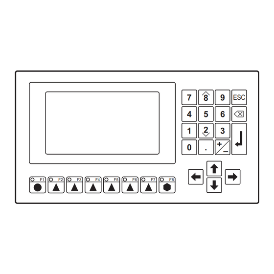
- Seite 4 3. Bedien- und Anzeigeelemente CR1008 ohne Numerik- Tastenblock Display grafikfähig, hinterleuchtet; Helligkeit und Kontrast einstellbar Numerik-Tastenblock zur Werte-Eingabe Cursortasten, in den Grundfunktionen mit folgender Belegung: = Menü beenden (Escape); = Menü öffnen / Eingaben bestätigen (Enter) = Cursortasten auf / ab, = Cursortasten nach links / nach rechts: Auswählen von Menüs oder Menüpunkten, Auswahl von Parametern, Verändern von Parameterwerten Funktionstasten (frei belegbar)
- Seite 5 Programmieren 1. Erstellen Sie das Arbeitsprogramm des tdm R 360 mit Hilfe des Editors ecolog tdm R 360 (Bestell-Nr. CP9005). Es enthält neben den Bedien- und Anzeigemenüs auch die Daten zur Konfiguration der CAN-Schnittstelle. 2. Verbinden Sie das tdm R 360 über die serielle Schnittstelle (RS232) oder über die CAN-Schnittstelle mit dem PC.
- Seite 6 7. Elektrischer Anschluß Schalten Sie die Anlage spannungsfrei und schließen Sie das Gerät über die Steck- verbindungen an. Anschlußbelegung s. Seite 8. Schließen Sie die AMP-Fahne mit einem 6,3 mm-Flachstecker an Masse an, damit die EMV-Bedingungen eingehalten werden. 8. Betrieb Funktionalität und Bedienung des tdm R 360 hängen ab von der Art der überwach- ten Anlage, von der Steuerung und vom Arbeitsprogramm, das für das tdm R 360 erstellt wurde.
- Seite 7 9. Technische Daten Anzeige Display LCD-Supertwist, grafikfähig, 240 x 128 Punkte, 127 x 68 mm Hintergrundbeleuchtung LED (Lebensdauer 100 000 h) Helligkeit / Kontrast einstellbar in 8 / 24 Stufen; temperaturkompensiert Darstellungsarten 4, 8 oder 16 Zeilen, Grafik und Text (mischbar) 10 / 20 / 40 Zeichen pro Zeile Zeichenhöhe [mm]: 14 / 7 / 4 Zeichensatz...
- Seite 8 10. Anschlußbelegung RS 232/ TTY CAN -BUS CAN- BUS / unit supply (CAN -BUS-supply) RxD + CAN - SHIELD CAN H +DC (unit supply) TxD + CAN -GND CAN -GND CAN H RxD– CAN L TxD– CAN L GND (unit supply) 11.
- Seite 10 1. Safety instructions • Observe the information of this document. Non-observance of the notes, oper- ation which is not in accordance with use as prescribed below, wrong installa- tion or handling can result in serious harm concerning the safety of persons and plant.
- Seite 11 3. Controls and visual indication CR1008 without numerical keypad Display with graphic capabilities, backlit, adjustable brightness and contrast Numerical keypad for the input of values with integrated cursor keys, the basic functions are allocated as follows: = exit menu (Escape); = open menu / confirm inputs (Enter) = cursor keys up /down, = cursor keys left/right: selection of menus or menu points,...
- Seite 12 Programming 1. Create the user program of the tdm R 360 by means of the editor ecolog tdm R 360 (order no. CP9005). In addition to the operator and visualisation menus it also contains the data to configure the CAN interface. 2.
- Seite 13 7. Electrical connection Disconnect the system and connect the module via the plug, see page 8 for wiring. Connect the AMP contact via a 6.3 mm flat-pin plug to ground to comply with the EMC requirements. 8. Operation The functions and use of the tdm R360 depend on the type of the system to be monitored, on the controller and the user program which was created for the tdm R 360.
- Seite 14 9. Technical data Display supertwisted LCD with graphic capabilities 240 x 128 points, 127 x 68 mm Background illumination LED (life 100,000 h) Brightness / contrast adjustable in 8 / 24 steps, temperature compensation Types of representation 4, 8 or 16 lines, graphics and text (can be mixed) 10/20/40 characters per line character height [mm]: 14 / 7 / 4 Set of characters...
- Seite 15 10. Wiring RS 232/TTY CAN -BUS CAN- BUS / unit supply (CAN - BUS -supply) RxD + CAN - SHIELD CAN H +DC (unit supply) TxD + CAN -GND CAN - GND CAN H RxD– CAN L TxD – CAN L GND (unit supply) 11.