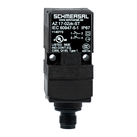
Werbung
Quicklinks
Montage- und Anschlussanleitung / Sicherheitsschalter
Mounting and wiring instructions / Safety Interlock Switch
Instructions de montage et de câblage / Interrupteur de sécurité
Hinweis
deutsch
Der elektrische Anschluss darf nur von autorisiertem Fachpersonal
durchgeführt werden. Die Konformitätserklärung nach Maschinen-
und Niederspannungsrichtlinie senden wir Ihnen auf Wunsch gerne
zu oder kann im Internet abgerufen werden. Weitere technische
Informationen entnehmen Sie bitte dem Schmersal Hauptkatalog
bzw. dem Online-Katalog im Internet unter www.schmersal.com.
Änderungen, die dem technischen Fortschritt dienen, vorbehalten.
Montage
Der Schalter kann in vier Richtungen ohne Umbaumaßnahmen
angebracht werden. Bei der Befestigung die mitgelieferten Unterleg-
bleche verwenden. Das Drehmoment der Befestigungsschrauben
darf 150 Ncm nicht überschreiten. Das Schaltergehäuse darf nicht
als Anschlag benutzt werden. Die Gebrauchslage ist beliebig. Sie
sollte so gewählt werden, dass kein grober Schmutz in die benutzte
Öffnung eindringen kann. Die nicht benutzte Öffnung nach der
Montage mit dem Schlitzverschluss verschließen. Bitte beachten Sie
auch die Hinweise der Normen EN 292, EN 953 und EN 1088.
Montage der Betätiger: Siehe Montageanleitung Betätiger
Verdrahtung und Abdichtung
Die Schneidklemmtechnik ermöglicht das Anschließen von flexiblen
Leitungen, Anschlussquerschnitt 0,75...1 mm
von Aderendhülsen. Hierzu die Leitung um 17...20 mm abmanteln,
in die Verschraubung einführen, die Verschraubung schließen, Adern
in die Stege des Deckels drücken (siehe Anschlussbild) und ansch-
ließend den Deckel aufschrauben. Dabei die Deckelschrauben
abwechselnd gleichmäßig anziehen.
Notice
english
The electrical connection may only be carried out by an authorized
person. The declaration of conformity according to the Machinery
and Low Voltage Directive can be mailed to you on request or can
be drawn from our website. For more technical information, please
refer to the Schmersal Main Catalogue or the online Catalogue on
our website www.schmersal.com.
Subject to technical modifications.
Mounting
The switch can be mounted in four different positions without re-
quiring any disassembly. When mounting the switch, the provided
L-shaped washers have to be used with the mounting screws.
Max. tightening torque 150 Ncm. The switch may not be used as
an endstop. The switch is suitable for any mounting position. It
should be selected in such a way, that no coarse dirt can fall into
Anschlussbild
Connection diagram
Illustration de raccordement
français
2
, ohne Verwendung
the used slot. The unused slots should be protected with the optio-
nal slotcaps. Please observe the instructions in the standards EN
292, EN 953 and EN 1088.
Mounting of the actuators: See mounting instructions actuators
Wiring and Sealing
The special cut-clamp technology allows the connection of
2
0.75 ... 1 mm
flexible wiring without using cable ends. Remove
approximately 17 ... 20 mm from the outer sleeve of the cable and
guide the wires into the cable gland opening. Tighten cable gland.
Press wires into the provided slots located on the inside of the
housing cover (see connections diagram). Re-tighten cover to
housing. Re-tighten the cover making sure the cover screws are
evenly tightened and the cover remains square.
Remarque
Le raccordement électrique doit être effectué uniquement par du
personnel technique habilité. Une attestation de conformité à la
directive Machines et Basse Tension peut vous être adressée sur
simple demande ou obtenue via Internet. Pour toute autre informati-
on technique, veuillez consulter le Catalogue principal de Schmersal
ou le Catalogue en ligne sur notre site Internet www.schmersal.com.
Sous réserve de modifications techniques.
Montage
L'interrupteur peut être fixé dans quatre directions sans aucun
démontage. Veuillez lors du montage à placer les rondelles sous les
têtes des vis de fixation, le couple de serrage ne peut pas dépasser
150 Ncm. Ne pas utiliser le boîtier de l'interrupteur comme butée.
La position d'utilisation est indifférente. Toutefois, elle doit être choi-
sie de manière à empêcher la pénétration de salissures grossières
dans l'orifice utilisé. Les orifices non utilisés doivent être obturés
après montage à l'aide des adhésifs obturateurs. Respecter égale-
ment les directives ou normes EN 292, EN 953 et EN 1088.
Montage des actionneurs: Voir les instructions de montage des
actionneurs
Câblage et étanchéité
La technique de raccordement simple à percement d'isolant permet
d'utiliser des fils souples, section de câble 0,75 ... 1 mm
embout. Pour cela, il suffit de dégainer le câble de connexion selon
l'illustration et de l'enfoncer en butée dans le presse-étoupe, de le
comprimer entre les nervures du couvercle (voir illustration de
raccordement) et de visser le couvercle.
AZ 17
AZ 17i
2
, sans
Werbung

Inhaltszusammenfassung für schmersal AZ 17
- Seite 1 EN 292, EN 953 et EN 1088. be drawn from our website. For more technical information, please refer to the Schmersal Main Catalogue or the online Catalogue on Montage des actionneurs: Voir les instructions de montage des our website www.schmersal.com.
- Seite 2 Kurzschlussschutz 6 A gG, D-Sicherung (DIN EN 60269-1) Short-circuit protection 6 A gG, D-fuse (DIN EN 60269-1) Protection contre les courts circuits 6 A gG, D-fussible (DIN EN 60269-1) K. A. Schmersal GmbH Telefon +49 - (0)2 02 - 64 74-0 Industrielle Sicherheitsschaltsysteme...
- Seite 3 La declaración de conformidad según directiva de Máquinas y Baja Tensión, puede suministrarse bajo demanda, o pueden obtenerse a través de Internet.Para mayor información, pueden consultar el Catálogo General de Schmersal. Pueden existir modificaciones debidas a mejoras técnicas. Montaje El interruptor puede ser montado en cuatro posiciones distintas, sin necesidad de desmontar.
- Seite 4 Istruzioni di montaggio ed allacciamento / Interruttore di sicurezza AZ 17 Instrucciones de montaje y cableado / Interruptor de Seguridad AZ 17i Manutenzione Contatti Italiano In caso di ambienti con utilizzo molto intenso consigliamo una Contactos manutenzione periodica con i seguenti punti: 1.


