Anmelden
Hochladen
Anleitungen
Marken
Bosch Anleitungen
Ladegeräte
TCE 5210
Bosch TCE 5210 Handbücher
Anleitungen und Benutzerhandbücher für Bosch TCE 5210. Wir haben
1
Bosch TCE 5210 Anleitung zum kostenlosen PDF-Download zur Verfügung: Instandsetzungsanleitung
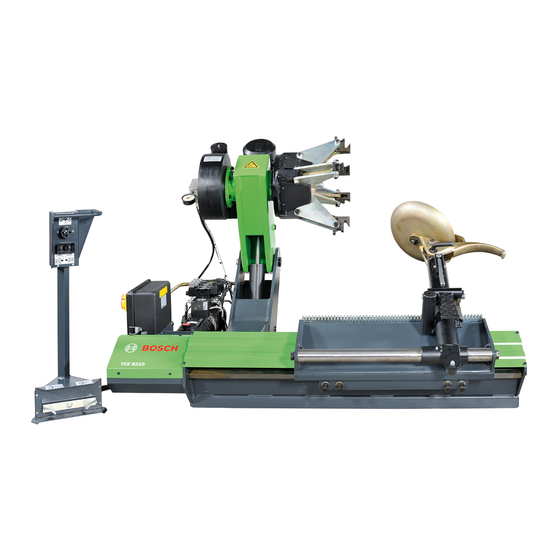
Bosch TCE 5210 Instandsetzungsanleitung (60 Seiten)
Marke:
Bosch
| Kategorie:
Ladegeräte
| Dateigröße: 0.94 MB
Inhaltsverzeichnis
Deutsch
4
Inhaltsverzeichnis
4
1 Verwendete Symbolik
5
Dokumentation
5
Tce 5210
5
2 Betriebsstörungen
6
3 Einstellungen
7
Prüfung und Wechsel der Drehrichtung der Elektromotoren
7
Manuelle Entsperrung der Magnetventile des Hydraulik-Steuergeräts
7
Austausch der Magnetventile des Hydraulik-Steuergeräts
7
Einstellung und Austausch des Antriebsriemens der Spannfutterwelle
8
Schmierpunkte
8
Einstellung der Arretierungen am Montagekopf-Arm
9
Elektrische Dreiphasenanlage
9
Q1 - Hauptschalter
9
F1, F2, F3 - Sicherungen zum Schutz des
9
Gesamten Hochspannungsschaltkreises
9
Q3 - Magnetothermischer Motorschutz- Schalter für den Schutz des Motors der Hydraulikpumpe
9
F4 und F5 - Sicherungen zum Schutz des Primärschaltkreises des Spannungsum- Wandlers (T 100VA)
9
F6 - Sicherung zum Schutz des Nieder- Spannungsschaltkreises mit 24VDC
9
F7 - Sicherung zum Schutz des Schaltkreises mit 24VAC
10
Elektrische Einphasenanlage
10
Q1 - Hauptschalter
10
F1 und F2 - Sicherungen zum Schutz des Hochspannungsschaltkreises Sowie des Motors für die Drehbewegung der Spann- Futterwelle
10
Q2 - Magnetothermischer Motorschutzschalter für den Schutz des Motors der Hydraulikpumpe
11
F4 und F5 - Sicherungen zum Schutz des Primärschaltkreises des Spannungsumwandlers (T 100VA)
11
F6 - Sicherung zum Schutz des Niederspannungsschaltkreises mit 24VDC
11
F7 - Sicherung zum Schutz des Schaltkreises mit 24VAC
11
Austausch der Joystick-Steuerung an der Pedal-Einheit
13
Austausch des Kabels Bzw. der Gesamten Pedal-Einheit
13
Austausch des Mikroschalters für die Drehbewegung der Spannfutterwelle in der Pedalsteuerung
14
Austausch der Kunststoffführungen am Schlitten des Montagekopfs
16
Vergleichende Tabelle der Hydrauliköle
17
English
18
Documentation
19
Symbols Used
19
Tce 5210
19
2 Malfunction
20
3 Adjustments
21
Test and Change of the Rotation Direction of the Electric Motors
21
Hydraulic Panel Electrovalve Release
21
Hydraulic Panel Electrovalve Replacement
21
Adjustment and Replacement of the Mandrel Rotation Belts
22
Greasing Points
22
Adjustments of the Hinges of the Tool Holding Arm
23
Three-Phase Electrical System
23
Q1 - Main Switch
23
F1, F2, F3 - Protection Fuses of the Whole
23
High-Tension Circuit
23
Q3 - Thermal-Magnetic Motor Protector for the Protection of the Motor and of the Hydraulic Pump
23
F4 and F5 - Protection Fuses of the Pri- Mary Circuit of the Tension Transformer (T 100VA)
23
F6 - Protection Fuse of the Low-Tension 24VDC Circuit
23
F7 Protection Fuse of the 24VAC Circuit
24
Single-Phase Electrical System
24
Q1 - Main Switch
24
F1 and F2 - Protection Fuses of the High-Tension Circuit and of the Mandrel Rotation Motor
24
Q2 - Thermal-Magnetic Motor Protector for the Protection of the Hydraulic Pump Motor
24
F4 and F5 - Protection Fuses of the Primary Circuit of the Tension Transformer (T 100VA)
24
F6 - Protection Fuse of the Low-Tension 24VDC Circuit
24
F7 - Protection Fuse of the 24VAC Circuit
25
Replacement of the Joystick of the Control Pedal Box
27
Replacement of the Pedal Box Cable and of the Entire Pedal Box
27
Replacement of the Micro Switch of the Control Pedal Box Rotation Mandrel
28
Replacement of the Spring of the Rocker Arm of the Control Pedal Box Rotation Mandrel
29
Replacement of the Tool Arm Trolley Slides
30
Oil Level Check
31
Español
32
Documentación
33
Símbolos Empleados
33
Tce 5210
33
2 Malfuncionamiento
34
3 Regulaciones
35
Verifi Cación y Cambio de Dirección de Rotación de Los Motores Eléctricos
35
Desbloqueo Electroválvulas Cetralita Oleodinámica
35
Sustitución Electroválvulas Centralita Oleodinámica
35
Regulación y Sustitución Correas de Rotación del Mandril
36
Puntos de Engrase
36
Regulación Escarpias Brazo Portaherramienta
37
Sistema Eléctrico Trifase
37
Q1 - Interruptor General
37
F1, F2, F3 - Fusibles de Protección del Circuito Completo de Alta Tensión
37
Q3- Salvamotor Magnetotérmico para la Protección del Motor de la Bomba Hidráu- Lica
37
F4 y F5 - Fusibles de Protección del Circuito Primario del Transformador de Tensión (T 100VA)
37
F6 - Fusible de Protección del Circuito de Baja Tensión a 24VDC
37
F7 - Fusible de Protección del Circuito
38
Vac
38
Sistema Eléctrico Monofase
38
Q1 - Interruptor General
38
F1 y F2 - Fusibles de Protección del Circuito de Alta Tensión y del Motor de la Rotación del Mandril
38
Q2 - Salvamotor Magnetotérmico para la Protección del Motor de la Bomba Hidráulica
38
F4 y F5 - Fusibles de Protección del Circuito Primario del Transformador de Tensión (T 100VA)
38
F6 - Fusible de Protección del Circuito de Baja Tensión a 24VDC
39
F7 - Fusible de Protección del Circuito
39
Vac
39
Sustitución Joystick Pedalera Comando
41
Sustitución Cable Pedalera Comando y Pedalera Completa
41
Sustitución del Micro de Rotación del Mandril de la Pedalera Comando
42
Sustitución Muelle Balanceador de Rotación Mandril Pedalera Comando
43
Sustitución de Los Patines del Carro del Brazo de la Herramienta
44
Italiano
46
Documentazione
47
Simboli Utilizzati
47
Tce 5210
47
2 Malfunzionamenti
48
3 Regolazioni
49
Verifi Ca E Cambio Verso DI Rotazione Motori Elett- Rici
49
Sblocco Elettrovalvole Centralina Oleodinamica
49
Sostituzione Elettrovalvole Centralina Oleodinamica
49
Regolazione E Sostituzione Cinghie Rotazione Mandrino
50
Punti DI Ingrassaggio
50
Regolazione Arpioni Braccio Porta Utensile
51
Impianto Elettrico Trifase
51
Q1 - Interruttore Generale
51
F1, F2, F3 - Fusibili DI Protezione Dell'intero Circuito Alta Tensione
51
Q3 - Salvamotore Magnetotermico Per la Protezione del Motore Della Pompa Idrau- Lica
51
F4 E F5 - Fusibili DI Protezione del Circuito Primario del Trasformatore DI Tensione (T 100VA)
51
F6 - Fusibile DI Protezione del Circuito DI Bassa Tensione a 24VDC
51
F7 Fusibile DI Protezione del Circuito 24VAC
52
Impianto Elettrico Monofase
52
Q1 - Interruttore Generale
52
F1 E F2 - Fusibili DI Protezione del Circuito Alta Tensione E al Motore Della Rotazione Mandrino
52
Q2 - Salvamotore Magnetotermico Per la Protezione del Motore Della Pompa Idraulica
52
F4 E F5 - Fusibili DI Protezione del Circuito Primario del Trasformatore DI Tensione (T 100VA)
52
F6 - Fusibile DI Protezione del Circuito DI Bassa Tensione a 24VDC
53
F7 - Fusibile DI Protezione del Circuito 24VAC
53
Sostituzione Joystick Pedaliera Comando
55
Sostituzione Cavo Pedaliera Comando E Pedaliera Completa
55
Sostituzione Micro Rotazione Mandrino Pedaliera Comando
56
Sostituzione Molla Bilanciere Rotazione Mandrino Pedaliera Comando
57
Sostituzione Pattini Carrello Braccio Utensile
57
Controllo Livello Olio
59
Werbung
Werbung
Verwandte Produkte
Bosch TS2-3
Bosch TS3-3
Bosch TS4-3
Bosch TS5-3
Bosch TS1-3 S
Bosch TS2-3 S
Bosch TS3-3 S
Bosch TS4-3 S
Bosch TS5-3 S
Bosch TCE 4220
Bosch Kategorien
Geschirrspüler
Waschmaschinen
Backöfen
Wäschetrockner
Kochfelder
Weitere Bosch Anleitungen
Anmelden
Anmelden
ODER
Mit Facebook anmelden
Mit Google anmelden
Anleitung hochladen
Von PC hochladen
Von URL hochladen