Inhaltsverzeichnis
Werbung
Verfügbare Sprachen
Verfügbare Sprachen
Short-form of Operating Instruction SOI/266-XC Rev. D
Short-form of Operating Instructions
for 266 pressure transmitters
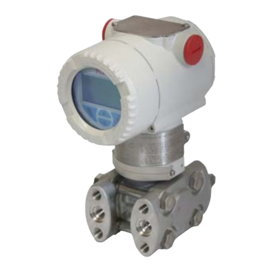
2600T Series Pressure Transmitters
Engineered solutions for all
applications
Language
English.........................................................................................................................................................................3
Italian...........................................................................................................................................................................25
German........................................................................................................................................................................47
French...........................................................................................................................................................................71
TTG Activation.............................................................................................................................................................94
Declaration of conformity.............................................................................................................................................95
Trouble Sheet........................................................................................................................................................................96
Return Report...........................................................................................................................................................................97
Page
Werbung
Kapitel
Inhaltsverzeichnis

Verwandte Anleitungen für ABB 2600T-Serie


Inhaltszusammenfassung für ABB 2600T-Serie
- Seite 1 Short-form of Operating Instruction SOI/266-XC Rev. D Short-form of Operating Instructions for 266 pressure transmitters 2600T Series Pressure Transmitters Engineered solutions for all applications Language Page English..................................3 Italian...................................25 German..................................47 French...................................71 TTG Activation................................94 Declaration of conformity.............................95 Trouble Sheet..................................96 Return Report...................................97...
- Seite 2 We are an established world force in the design and manufacture of measurement products for industrial process control, flow measurement, gas and liquid analysis and environmental applications. As a part of ABB, a world leader in process automation technology, we offer customers application expertise, service and support worldwide.
-
Seite 3: Inhaltsverzeichnis
This document provides basic instruction for the installation and potentially damaging situation. Failure to avoid this could result in commissioning of the ABB 2600T pressure transmitter. This damage to the product or its surrounding area. transmitter is connected to a process by means of impulse lines and can measure Pressure, Differential pressure or Absolute pressure. -
Seite 4: Product Identification
1 Introduction 1.5 Product identification The certification plate (ref.A) shown here is issued by ABB S.p.A, 22016 Lenno, Italy, with the numbers: The instrument is identified by the data plates shown in Figure 1. The certification plate (ref. A): contains the certification —... -
Seite 5: Safety
There is no limit to the storage period, although the terms of guarantee remain as agreed with the Company and as given in All obligations of ABB Instrumentation result from the respective the order acknowledgement. sales contract which also comprises the complete and solely valid warranty clauses. -
Seite 6: Installation
ATEX TYPE “N” / EUROPE: by existing or foreseeable aggressive substances. ABB cannot guarantee that a construction material is suited to a particular — II 3 G Ex nL IIC T4/T5/T6 and II 3 D Ex tD A22 IP67 T85°C process fluid under all possible process conditions. - Seite 7 The data label includes the back the LCD module on the communication board. Be sure following specifications: that the 4 plastic fixing locks are properly in place. SERIAL\NUMBER ABB S.p.A. Made in Italy PRODUCT CODE SEAL-L SEAL-H SPEC.REQUEST...
-
Seite 8: Electrical Connection
3 Installation 3.8 Electrical connection 3.8.2 Electrical requirements – PROFIBUS PA PROFIBUS-PA transmitters are provided for the connection to The relevant guidelines must be observed during the electrical segment couplers DP/PA. The permissible voltage at the installation! Since the transmitter has no switch-off elements, it terminals is DC 9 - 32 V (9 - 17,5 V for FISCO). - Seite 9 3 Installation 3.11 Wiring Follow these steps to wire the transmitter: — Remove the cap from one of the two electrical connection ports located at both sides in the upper part of the transmitter housing. — These connection ports have a 1/2 inch internal NPT threads.
-
Seite 10: Transmitter Configuration
Push the zero (Z) button on top of the transmitter for the complete “Operating Instruction” available online at at least 3 seconds. www.abb.com. The output will go to 4 mA, and if the Integral Display If the AI Block cannot be removed from OOS mode, please is present, the message “OPER DONE”... -
Seite 11: Absolute Pressure Transmitter Re-Zeroing
4 Transmitter configuration 4.6 Hardware settings 4.5.2 Absolute pressure transmitter re-zeroing Absolute pressure transmitter rezeroing is only possible when a 4.6.1 HART vacuum pressure generator is available. It is strongly There are 6 dip switches located on this kind of secondary recommended to refer to the integral manual before electronics (as indicated by the figure);... - Seite 12 4 Transmitter configuration power up the transmitter. Switch 2 up in “1” position indicates 4.6.2 PROFIBUS PA that a new sensor has been installed. There are 3 dip switches located on this kind of secondary electronics (as indicated by the figure); they are used for AFTER ANY REPLACE OPERATION IT IS RECOMMENDED TO settings when integral display is not available.
- Seite 13 4 Transmitter configuration 4.7.4 Define the PV Unit Important. In case of PA or FF pressure transmitters, please If the desired Process Variable Unit is different from the consider as mandatory the following steps. indicated, select Edit then scroll the desired unit (see the following table) with the up and down keys and confirm with 4.7.10 Define the OUT unit OK.
-
Seite 14: Applications
5 Applications 5 Applications 5.1 Steam (condensable vapor) or clean liquids flow measurement — Place taps to the side of the line. — Mount beside or below the taps. — Mount the drain/vent valve upward. In case of steam application fill the vertical section of the connecting lines with a compatible fluid through the dedicated filling tees because the process fluid must enter the transmitter measuring chambers. -
Seite 15: Pressure Or Absolute Pressure Measurement Of A Condensable Vapor In A Pipe
5 Applications 5.4 Liquid level measurement with open tanks — Mount the transmitter at the same height or below the lowest level to be measured. — Connect the + (H) side of the transmitter to the bottom of the tank. —... -
Seite 16: Diaphragm Seals
Properly position the gasket so that it does not tpress down the diaphragm. A gasket not properly installed may affect the ABB sanitary seals may be supplied with a 3A symbol which is transmitter measurement. When installing flushing rings make printed on the seal body. -
Seite 17: Hazardous Area Considerations
7 Hazardous area considerations 7 Hazardous Area considerations 7.1 Ex Safety aspects and IP Protection (Europe) Important. The number close to the CE marking of the transmitter According to ATEX Directive (European Directive 94/9/EC of 23 safety label identifies the Notified Body which has responsibility for March 1994) and relative European Standards which can the surveillance of the production. - Seite 18 7 Hazardous area considerations b) Certificate ATEX II 1/2 G Ex ia IIC T4/T5/T6 and (Note: the number close to the CE marking of the transmitter safety label identifies the Notified Body which has responsibility II 1/2 D Ex iaD 21 T85°C for the surveillance of the production) FM Approvals certificate number The other marking refers to the protection type used according...
- Seite 19 7 Hazardous area considerations c) Certificate ATEX II 1/2 G Ex d IIC T6 The other marking refers to the protection type used according to relevant EN Standards: ATEX II 1/2 D Ex tD A21 IP67 T85°C (-50°C ≤ Ta ≤+75°C) —...
- Seite 20 (corresponding to 100°C max) with a Ta from -50°C to +40°C — T6: Temperature class of the transmitter Important. It is the technical support for the ABB Declaration of (corresponding to 85°C max) with a Ta from -50°C to +40°C Conformity About the applications, this transmitter can be used in “Zone 2”...
-
Seite 21: Applicable Standards
7 Hazardous area considerations 7.1.1 Entities for “L5” option (display with TTG technology) 7.2.2 Classifications The 2600T Series pressure transmitters have been certified by HART Version with “L5” option (display TTG) FM Approvals for the following Class, Divisions and Gas Ui= 30Vdc Ci= 5nF Li= uH... -
Seite 22: Safety Manual
8 Safety manual 8 Safety manual Safety Planning. Additional instruction for IEC61508 certified device (digits 8 or T under “output” options) The Safety Planning shall consider: 8.1 Safety philosophy — policies and strategies for achieving safety; The 266 Pressure Transmitters are field devices designed —... - Seite 23 8 Safety manual 8.11 Safety requirement allocation 8.14 Architecture description and principle of operation Each safety function, with its associated safety integrity The instrument consists of two main functional units: requirement, shall be allocated to the designated safety related systems taking into account the risk reductions achieved by the —...
- Seite 24 8 Safety manual 8.18 Proof tests 8.19 Safety-related parameters Safe undetected faults could occur during the operation of the The Safety 266 pressure transmitters product meets the SIL2 transmitters. These failures do not affect the transmitter requirements of IEC 61508 in low as well as high demand operations.To maintain the claimed Safety Integrity Level (SIL 2) mode of operation.
- Seite 25 Altri documenti aggiornati possono essere scaricati dal sito: — I composti chimici devono essere lontani da fonti di calore www.abb.com/pressure e protetti da temperature estreme, mentre le polveri devono mantenersi asciutte. Se richiesta la 1.3 Significato delle istruzioni movimentazione devono essere adottate le normali procedure di sicurezza.
-
Seite 26: Identificazione Del Prodotto
1 Introduzione 1.5 Identificazione del prodotto La targhetta certificativa (rif. A) qui sotto viene emessa da ABB S.p.A, 22016 Lenno, Italia, e può riportare i seguenti numeri: Lo strumento è identificato tramite varie targhette come illustrato in figura 1. —... -
Seite 27: Generalità
Società e specificati nella conferma d’ordine. Tutti gli obblighi di ABB derivano dal rispettivo contratto di vendita valido di volta in volta, il quale contiene anche il regolamento di garanzia completo e unicamente valido. Tali clausole di garanzia contrattuali non vengono limitate e neppure ampliate dal contenuto delle presenti istruzioni per l’uso. -
Seite 28: Considerazioni Per Applicazioni In Aree Pericolose
ATEX EXPLOSION PROOF L’identificazione delle corrette connessioni di processo dovrà avvenire con attenzione. ABB non può garantire che un materiale — II 1/2 G Ex d IIC T6 and II 1/2 D Ex tD A21 IP67 T85°C sia adatto a particolari fluidi di processo in tutte le possibili condizioni. -
Seite 29: Rispetto Della Direttiva Sulle Attrezzature In Pressione (97/23/Ce)
Riagganciare in fine l’LCD e sono stati sottoposti ad una valutazione di conformità. La assicurarsi che i quattro fermi in plastica siano correttamente in targhetta include i seguenti dati tecnici: sede. NUMERO ABB S.p.A. SERIALE Made in Italy CODICE SEP.-BASSA SEP.-ALTA ID SPECIALE Rev. -
Seite 30: Connessioni Elettriche
3 Installazione 3.8 Connessioni elettriche 3.8.2 Requisiti di natura elettrica - PROFIBUS - PA I trasmettitori con protocollo PROFIBUS PA sono previsti per il Rispettare le norme vigenti durante l’installazione elettrica. collegamento ad accoppiatori di segmenti DP/PA. La tensione Poiché il trasmettitore non dispone di elementi di disinnesto, è ai morsetti consentita è... - Seite 31 3 Installazione 3.11 Cablaggio Seguire i punti in successione per il cablaggio del trasmettitore: — Rimuovere i tappi di plastica temporanei, da uno o entrambi gli accessi per le connessioni elettriche, presenti sui lati nella parte superiore dell’housing del trasmettitore. —...
- Seite 32 3 secondi. Fieldbus, fare riferimento al manuale completo disponibile online L’uscita passa a 4 mA e, se presente il display sul sito www.abb.com. integrale, compare il messaggio “OPER DONE” (operazione eseguita). Se non succede niente Nel caso in cui la funzione AI non riuscisse a uscire dallo stato verificare l’interruttore di protezione scrittura;...
-
Seite 33: Riazzeramento Dello Strumento Di Pressione Assoluta
4 Configurazione del trasmettitore 4.6 Impostazioni hardware 4.5.2 Riazzeramento dello strumento di pressione assoluta Questa operazione definita come “riazzeramento” è eseguibile 4.6.1 HART solamente tramite un generatore di pressione di vuoto. Prima di Ci sono 6 microinterruttori posizionati sull’elettronica procedere con questa operazione viene consigliato di riferirsi al secondaria che vengono utilizzati per eseguire varie operazioni manuale d’istruzione integrale. -
Seite 34: Installazione Guidata
4 Configurazione del trasmettitore Modalità di sostituzione (microinterruttori 1 e 2) 4.6.2 PROFIBUS PA I microinterruttori 1 e 2 permettono l’operazione di sostituzione Normalmente i microinterruttori 1 e 2 sono nella posizione di “REPLACE MODE” dell’elettronica secondaria e/o del “0” e vengono posizionati diversamente solo in caso di trasduttore (sensore). - Seite 35 4 Configurazione del trasmettitore 4.7.4 Definire l’Unità Ingegneristica della PV 4.7.8 Definire il punto di linearizzazione Se l’unità ingegneristica di pressione (Unità Pressione) risulta Per la funzione di trasferimento a radice quadrata, se il punto di diversa da quella impostata dalla fabbrica, selezionare Modifica linearizzazione desiderato è...
- Seite 36 5 Applicazioni 5 Applicazioni 5.1 Misura di portata per liquidi puliti o vapori (condensabile) — Derivare le prese a fianco della linea — Montare a lato o sotto le prese — Montare la valvola di spurgo a monte della flangia Nel caso di applicazione con vapore riempire la sezione verticale delle linee di connessione con un fluido compatibile, utilizzando gli attacchi di riempimento dedicati.
- Seite 37 5 Applicazioni 5.4 Misura di livello su serbatoi aperti — Montare il trasmettitore alla stessa altezza o sotto il minimo livello da misurare. — Connettere il lato + (H) del trasmettitore al fondo del serbatoio. — Lasciare il lato “–” (L) del trasmettitore all’atmosfera (in questa immagine viene mostrato un trasmettitore di pressione relativa il cui lato “–”...
- Seite 38 Inoltre, in questo caso specifico, è I separatori sanitari ABB possono essere forniti con il simbolo indispensabile allineare perfettamente l’anello alla superficie di 3A stampato sul corpo del separatore stesso. Al fine di tenuta della guarnizione.
- Seite 39 7 Considerazioni per aree pericolose 7 Considerazioni per aree classificate 7.1 Aspetti di “sicurezza EX” e protezione IP (Europa) Nota. l numero vicino al marchio CE della targhetta di sicurezza In accordo alle Direttive ATEX (Direttive Europee 94/9/EC del 23 identifica l’Ente che effettua la sorveglianza sulla produzione del marzo 19949 e relativi Standard europei che possono trasmettitore.
- Seite 40 7 Considerazioni per aree pericolose b) Certificato ATEX II 1/2 G Ex ia IIC T4/T5/T6 e Nota. l numero vicino al marchio CE della targhetta di sicurezza II 1/2 D Ex iaD 21 T85°C identifica l’Ente che effettua la sorveglianza sulla produzione del trasmettitore.
- Seite 41 7 Considerazioni per aree pericolose c) Certificato ATEX II 1/2 G Ex d IIC T6 Nota. l numero vicino al marchio CE della targhetta di sicurezza ATEX II 1/2 D Ex tD A21 IP67 T85°C (-50°C ≤ Ta ≤+75°C) identifica l’Ente che effettua la sorveglianza sulla produzione del trasmettitore.
- Seite 42 7 Considerazioni per aree pericolose In accordo alle Direttive ATEX (Direttive Europee 94/9/EC del 23 Il significato del codice ATEX è come segue: marzo 1994) e relativi Standard europei che possono — II: Gruppo per aree di superficie (non miniere) assicurare la compatibilità...
- Seite 43 7 Considerazioni per aree pericolose 7.1.1 Entità per display opzionale L5 7.2.2 Classificazioni (HMI con tecnologia TTG) I trasmettitori di pressione della serie 2600T sono stati certificati HART per i seguenti gruppi categorie, elementi di atmosfera Ui= 30Vdc Ci= 5nF Li= uH pericolosa, classi di temperatura, tipi di protezione.
- Seite 44 8 Manuale di sicurezza 8 Manuale di sicurezza La pianificazione di sicurezza includerà: Istruzioni aggiuntive per strumenti certificati IEC 61508 (digit 8 o T in opzioni “uscita”) — regole e strategie per raggiungere lo stato di sicurezza 8.1 Concetto di sicurezza —...
- Seite 45 8 Manuale di sicurezza 8.11 Allocazione dei requisiti di sicurezza 8.14 Descrizione dell’architettura e principio di funzionamento Ciascuna funzione di sicurezza,con i relativi requisiti di integrità, Lo strumento consiste di due unità funzionali principali: dovrà essere allocata al sistema designato tenendo in considerazione la riduzione di rischio ottenuta dalle altre —...
-
Seite 46: Parametri Di Sicurezza
8 Manuale di sicurezza 8.18 Proof tests 8.19 Parametri di sicurezza I guasti sicuri non identificati possono accadere durante I trasmettitori 266 sono adatti all’utilizzo in loop SIL2, grazie alla l’operatività dello strumento. Questi guasti non affliggono la conformità alla IEC 61508 per quasiasi requisito operativo. Il funzionalità... -
Seite 47: Einführung
Informationen. Dies ist kein Hinweis auf eine gefährliche Dieses Dokument enthält grundlegende Anweisungen für die oder schädliche Situation. Installation und Inbetriebnahme des Druckmessumformers ABB 2600T. Dieser Messumformer wird über Impulsleitungen an einen Prozess angeschlossen und kann Druck, Vorsicht – <Leichte Verletzungen>. Dieses Symbol in Verbindung Differenzdruck oder Absolutdruck messen. -
Seite 48: Gesundheit Und Sicherheit
Ausgangssignal, den Membranwerkstoff, die Füllflüssigkeit, die Bereichsgrenzen, die Seriennummer, den maximalen Betriebsdruck (PS) und die maximale Betriebstemperatur (TS). Bitte geben Sie bei Anfragen an den ABB Service immer die Seriennummer des Gerätes an. Das optionale zusätzliche Kennzeichnungsschild aus nichtrostendem Stahl (Angabe C - code I2) gibt die Nummer des Messstellenkennzeichens des Kunden sowie die eingestellte Messspanne an. - Seite 49 FM09ATEX0025X 0722 CL I/DIV2/GP ABCD NIFW when connected per drawing APPROVED IECEx FME09.0004X "FNICO Field Instrument" DH 3173 ENCL 4X "FNICO Field Instrument" - "DUAL SEAL" Abb. 1: Produktidentifikation Druckmessumformer der Reihe 2600T Modelle 266 | SOI/266-XC Rev. D 49...
-
Seite 50: Allgemeines
Das Instrument erfordert bei der Handhabung keine zur Änderung dieser erstellt ist. Sämtliche Verpflichtungen von besonderen Vorkehrungen, übliche Vorgehensweisen sollten ABB Instrumentation ergeben sich aus dem entsprechenden jedoch beachtet werden. Kaufvertrag, der auch die vollständigen und alleine gültigen Gewährleistungsklauseln enthält. Diese vertraglichen 2.4 Lagerung... -
Seite 51: Installation
Sensor mit den beiliegenden Verschlussschrauben (1/4-18 oder absehbar vorhandenen aggressiven Stoffen ausgesetzt sein NPT) verschließen. Hierfür den offiziell zugelassenen kann. ABB kann nicht garantieren, dass ein Werkstoff für ein Dichtungswerkstoff verwenden. bestimmtes Prozessmedium unter allen möglichen Prozessbedingungen geeignet ist. Die Füllflüssigkeiten und 3.3 Wichtige Punkte zu explosionsgefährdeten... -
Seite 52: Einhaltung Der Druckgeräterichtlinie (97/23/Ce)
Sicherheitsvorschriften und treffen Sie die entsprechenden Sicherheitsmaßnahmen. 3.4 Einhaltung der Druckgeräterichtlinie (97/23/CE) Abb. 3: Drehbares Gehäuse 3.4.1 Geräte mit PS >200 bar 3.6 Drehen der integrierten LCD-Anzeige Geräte mit einem zulässigen Druck von PS > 200 bar wurden einer Konformitätsprüfung unterzogen. -
Seite 53: Elektrischer Anschluss
3 Installation 3.7 Anschluss der Wirkdruckleitungen für Eine geöffnete Abdeckung bietet keinen Berührungsschutz. Standardgeräte Keine leitfähigen Bauteile berühren. Prüfen, ob die vorhandene Betriebsspannung mit der auf dem Typenschild angegebenen Um die korrekte Verlegung der Leitungen sicherzustellen, sind Betriebsspannung übereinstimmt. Für die folgende Punkte zu beachten: Spannungsversorgung und für das Ausgangssignal werden —... -
Seite 54: Verdrahtung
Anschlussklemme für die Erdung (PE) ist außen am Messumformer und auch im Stecker vorhanden. Beide Klemmen sind elektrisch leitend verbunden. Abb. 5: HART- und PROFIBUS – Fielbus-Kommunikation 3.10 Messumformer mit integriertem Überspannungsschutz Mit einem kurzen Draht das Messumformergehäuse über den Erdungsanschluss (PA) mit dem Potenzialausgleich verbinden. -
Seite 55: Messumformer-Konfiguration
— OUT_SCALE: Output range (alle zulässigen Einheiten) — L_TYPE: Direct, Indirect or Square Root Hinweis. Weitere Information für FOUNDATION Fieldbus-Geräte finden Sie in der “Zusatzdokumentation” oder www.abb.com. Wenn der AI-Block nicht aus dem OOS-Modus genommen werden kann, siehe unten stehende Tabelle: Mögliche Ursache... -
Seite 56: Nullpunkteinstellung Bereits Kalibrierter Geräte
(z.B. 4 .. 20 mA = - 100 .. 100 mbar) 1. Den Messumformer vom Prozess isolieren und die Messwerkskammer/n gegen Atmosphäre entlüften. Abb. 6: Schreiben aktiviert und deaktiviert 2. Vom Prozess oder Druckgeber Druck für den Messanfang vorgeben (4 mA). Der Druck muss stabil und mit hoher Genauigkeit (<... -
Seite 57: Hardwareeinstellungen
4 Messumformer-Konfiguration 4.6 Hardwareeinstellungen 4.6.1 HART Schalter 1 und 2 ermöglichen den AUSTAUSCH-Modus Auf der Sekundärelektronik sind 6 DIP-Schalter (wie im Bild) (REPLACE MODE) für Sensor und Sekundärelektronik (NEW angebracht; sie werden für die Einstellung genutzt, wenn ein SENSOR / NEW ELECTRONIC). LCD-Anzeiger nicht vorhanden ist. -
Seite 58: Einfache Konfiguration
4 Messumformer-Konfiguration Austausch Modus / Replace mode (Schalter 1 und 2) 4.7.3 Messstellenkennzeichen (Tag) einfügen Falls die Tag-Nummer des Geräts von dem im Werk Normalerweise stehen die Schalter 1 und 2 in Position “0”. Sie voreingestellten abweicht, ist dieser Teil des Easy-Setup-Menüs werden betätigt, wenn ein Austauschvorgang notwendig ist. - Seite 59 4 Messumformer-Konfiguration 4.7.7 Linearisierungstyp definieren 4.7.13 Dämpfung definieren Wenn der gewünschte Dämpfungswert vom angezeigten Wenn der gewünschte Linearisierungstyp vom angezeigten abweicht, Bearb. auswählen und zum gewünschten abweicht, kann er mit den Tasten “auf” und „“ab“ geändert und Linearisierungstyp scrollen, anschließend mit OK bestätigen. mit OK bestätigt werden.
-
Seite 60: Installationsvarianten
5.2 Durchflussmessung von Gasen oder Flüssigkeiten (mit Feststoffen in Suspension) — Entnahmestellen oben oder seitlich an der Prozessleitung vorsehen. — Den Messumformer oberhalb der Entnahmestellen montieren. Abb. 9: Füllstandsmessung an geschlossenen Behältern 60 SOI/266-XC Rev. D | Druckmessumformer der Reihe 2600T Modelle 266... -
Seite 61: Füllstandsmessung An Offenen Behältern Mit
— Die Messzelle des Modells 266HSH / 266NSH kann über das eingebaute Entlüftungsventil in die Atmosphäre entlüftet werden. Abb. 10: Füllstandsmessung an offenen Behältern 5.5 Druck- oder Absolutdruckmessung von Flüssigkeiten in einer Prozessleitung — Entnahmestellen seitlich an der Prozessleitung vorsehen. -
Seite 62: Membrandruckfühler
— Messumformer mit Membrandruckfühlern verlangen werden. In Zweifelsfällen lesen Sie die vollständige besondere Aufmerksamkeit bei der Handhabung und Betriebsanleitung, die per Download unter www.abb.com oder Installation, um Gerätebeschädigungen zu vermeiden. über Ihren ABB Instrumentation-Händler erhältlich ist. — Messumformer mit Kapillarrohren (Überdruck oder Differenzdruck) beim Anheben nicht an den Kapillarrohren 6.5 Zellen (Sandwitch) Druckfühler (Modell S26W) -
Seite 63: Anforderungen Für Explosionsgefährdete Bereiche
7 Anforderungen für explosionsgefährdete Bereiche 7 Anforderungen für explosionsgefährdete Bereiche Der ATEX-Code hat folgende Bedeutung: 7.1 “Ex-Schutz”-Anforderungen und “IP-Schutzart” (Europa) — II: Gerätegruppe für oberirdische explosionsgefährdete Entsprechend der ATEX-Richtlinie (Europäische Richtlinie Bereiche (nicht in Bergwerken) 94/9/EG vom 23. März 1994) und geltender Europäischer —... - Seite 64 7 Anforderungen für explosionsgefährdete Bereiche b) Zertifikat ATEX II 1/2 G Ex ia IIC T4/T5/T6 und II 1/2 D Ex iaD Hinweis. Die Zahl neben der CE-Kennzeichnung des 21 T85°C Ex-Typenschildes des Messumformers gibt die zuständige Behörde FM Zulassungen mit der Nummer an, die für die Produktionsüberwachung zuständig ist.
- Seite 65 7 Anforderungen für explosionsgefährdete Bereiche c) Zertifikat ATEX II 1/2 G Ex d IIC T6 - Die andere Kennzeichnung bezieht sich auf die Schutzart entsprechend der relevanten EN-Normen: ATEX II 1/2 D Ex tD A21 IP67 T85°C (-50°C ≤ Ta ≤+75°C) —...
- Seite 66 Oberflächentemperatur 85 °C) mit einer Ta von Hinweis. Dies ist die technische Grundlage der -50 °C bis +40 °C ABB-Konformitätserklärung Dieser Messumformer kann wie in den folgenden Skizzen gezeigt in den als “Zone 2” (Gas) und “Zone 22” (Staub) Hinweis.
-
Seite 67: Elektrische Daten Für "L5" Optionale Integrierte Lcd Anzeige (Hmi Mit Ttg Technologie)
7 Anforderungen für explosionsgefährdete Bereiche 7.1.1 Elektrische Daten für “L5” optionale integrierte LCD 7.2.2 Klassifikationen Anzeige (HMI mit TTG Technologie) Die Druckmessumformer der Reihe 2600T sind von FM HART bescheinigt für folgende “Class”, “Divisions” und “Gas groups”, Ui= 30Vdc Ci= 5nF Li= uH “Hazardous classified locations”, “Temperature class”... -
Seite 68: Sicherheitsanweisungen
8 Sicherheitsanweisungen 8 Sicherheitsanweisungen 8.5 Management der Funktionalen Sicherheit Zusätzliche Hinweise für nach IEC61508 zertifizierte Geräte (*Ziffern 8 oder T unter Ausgangsoptionen) Für jede Anwendung muss der Installateur oder Eigentümer eines Sicherheitssystems einen Sicherheitsplan erstellen, der 8.1 Sicherheitsphilosophie über den gesamten Lebenszyklus des mit Die Druckmessumformer der Modelle 266 sind als Feldgeräte Sicherheitsinstrumentierung ausgestatteten Systems zu gemäß... - Seite 69 8 Sicherheitsanweisungen Die Gesamtansprechzeit des Systems muss geringer als die — Überdruck, hohe Druckspitzen in den Prozessleitungen Prozesssicherheitszeit sein. Um den sicheren Betrieb des — Eindringen von Wasserstoff in die Füllflüssigkeit, Systems zu gewährleisten, muss das Produkt aus der Membranriss bei Anwendungen mit Wasserstoff als Abtastrate jedes Bereichs des Logikanalysators und der Anzahl Prozessmedium der Kanäle zusammen mit der Sicherheitszeit des Stellgliedes...
-
Seite 70: Aktivierung Und Deaktivierung Des Betriebsmodus
8 Sicherheitsanweisungen — Messumformer wieder einschalten: Das Gerät führt ein Impulsbreitensignal umgewandelt. Das Signal wird gefiltert und aktiviert dann den 4 … 20 mA-Umformer. In dieser Einheit automatisch einen Selbsttest durch, der folgende Tests ist auch die bidirektionale digitale Kommunikation unter umfasst: Verwendung des HART-Standardprotokolls implementiert. -
Seite 71: Introduction
Le présent document donne des instructions de base pour situation dangereuse ou préjudiciable. l’installation et la mise en service du transmetteur de pression ABB 2600T. Ce transmetteur est connecté à un processus par des lignes d’impulsions et peut mesurer la pression, la Ce pictogramme associé à la Attention –... -
Seite 72: Hygiène Et Sécurité
1 Introduction 1.4 Hygiène et sécurité La plaque de certification présentée ci-dessous (réf. A) est imprimée par ABB S.p.A. 22016 Lenno, Italie, avec les Afin d’assurer l’absence de risque et le respect des règles numéros suivants : d’hygiènes, les points suivants doivent être pris en compte dans l’utilisation de nos produits:... - Seite 73 1 Introduction NUMÉRO ABB S.p.A. DE SÉRIE Fabriquè en Italie CODE PRODUIT SÉP-H SÉP-B DEMANDE SPÈC. Rèv.HW MEMBR.-REMPL. CELLULE BRIDE/CONNEX.-JOINTS H MEMBR.-REMPL. B MEMBR.-REMPL. PED: ALIMENTATION SIGNAL DE SORTIE PRES.MAX.SERV. LSG/LIG LIMITES DE MISURE Clavie local sous le plaque 2600T Repère...
-
Seite 74: Sécurité
à modifier aucun de ceux-ci. Toutes les ambiantes spécifiées. La durée de stockage n’est pas limitée, obligations d’ABB Instrumentation découlent du contrat de mais les conditions de garantie convenues avec la société et vente, qui inclut l’intégralité des seules clauses de garantie exposées dans l’acceptation de commande restent... -
Seite 75: Installation
Les transmetteurs de la série 266 sont disponibles avec les exposé aux effets actuels ou prévisibles de substances agressives. certifications suivantes : ABB ne peut pas garantir qu’un matériau de construction SÉCURITÉ INTRINSÈQUE ATEX conviendra pour un produit de process donné et dans toutes les conditions de process possibles. -
Seite 76: Rotation Du Boîtier
Les appareils dont la pression autorisée PS dépasse 200 bars verrous en plastique sont remis correctement. ont fait l’objet d’une validation de conformité. L’étiquette d’information donne les indications suivantes : NUMÉRO ABB S.p.A. DE SÉRIE Fabriquè en Italie CODE PRODUIT SÉP-B SÉP-H... -
Seite 77: Branchements Électriques
3 Installation Plusieurs types de barrières de sécurité passives ou actives — Poser les prises de pression de telle sorte que les bulles peuvent être utilisées de façon satisfaisante en conjonction de gaz (pour la mesure de fluides) ou la condensation (pour la mesure de gaz) puissent retourner dans la avec le transmetteur Smart 2600T. - Seite 78 3 Installation 3.9 Conducteur de protection/mise à la terre Le transmetteur fonctionne avec la précision spécifiée sous une tension en mode commun de 250 V au maximum entre les lignes de signal et le boîtier. Afin d’assurer la conformité aux exigences des directives sur les basses tension et aux dispositions pertinentes de la norme EN 61010 sur l’installation des composants électriques, le boîtier doit être muni d’un...
-
Seite 79: Configuration Du Transmetteur
FOUNDATION, se reporter au mode d’emploi dediqué ou consulter Appuyer sur le bouton du zéro (Z) sur le transmetteur le site www.abb.com. pendant au moins 3 secondes. Si le bloc AI ne peut pas être retiré du mode OOS, se reporter La sortie passe à... - Seite 80 4 Configuration du transmetteur 4.5.2 Remise à zéro d’un transmetteur de pression absolue La remise à zéro du transmetteur de pression absolue n’est possible que lorsqu’un générateur de pression à vide est disponible. Il est fortement recommandé de se reporter au manuel intégré...
-
Seite 81: Réglage Rapide
4 Configuration du transmetteur — Mode de remplacement (commutateurs 1 et 2) — Mode erreur (commutateurs 4 et 5) Si l’utilisateur modifie les paramètres définis en usine pour un Les commutateurs 1 et 2 sont généralement sur la position « 0 ». - Seite 82 4 Configuration du transmetteur 4.7.4 Définir l’unité de la variable du procdé (PV) 4.7.9 Définir la valeur « Low Flow Cut Off » Si le « Low Flow Cut Off » souhaité pour une fonction de Si l’unité PV souhaitée est différente de celle indiquée, sélectionner Edit, puis choisir l’unité...
-
Seite 83: Applications
5 Applications 5 Applications Le fluide de procédé doit entrer par le côté primaire du 5.1 Mesure de débit de liquides propres ou de vapeur (vapeur condensable) transmetteur : — Placer les robinets sur le côté de la conduite. — Ouvrir la vanne d’équilibrage (C) —... - Seite 84 5 Applications 5.4 Mesure de niveau de liquide dans des réservoirs ouverts — Monter le transmetteur à la même hauteur ou en-dessous du niveau de liquide à mesurer le plus bas. — Raccorder le côté + (H) du transmetteur au bas du réservoir.
-
Seite 85: Séparateurs À Membrane
Avant de procéder à l’installation, s’assurer de la compatibilité des matériaux mouillés avec le process. 6.8 Séparateurs sanitaires (modèle S26S) Les séparateurs sanitaires ABB peuvent être fournis avec un En cas d’installation d’un séparateur à membrane nécessitant symbole 3A imprimé. Pour installer correctement les un joint (S26CN, S26F, S26J, S26M, S26P, S26R, S26S, S26U, séparateurs certifiés 3A, se reporter à... -
Seite 86: Zones Dangereuses
7 Zones dangereuses 7 Zones dangereuses 7.1 Aspects « Sécurité EX » et protection « IP » (Europe) Signification du code ATEX : Conformément à la directive ATEX (directive européenne — II: Groupe pour les surfaces actives (hors mines) 94/9/CE du 23 mars 1994) et aux normes européennes —... - Seite 87 7 Zones dangereuses Les autres marquages se réfèrent à l’indice de protection utilisé b) Certificat ATEX II 1/2 G Ex ia IIC T4/T5/T6 et conformément aux normes EN correspondantes : II 1/2 D Ex iaD 21 T85°C Homologations FM, numéros de certificat respectifs : —...
- Seite 88 7 Zones dangereuses c) Certificat ATEX II 1/2 G Ex d IIC T6 Les autres marquages se réfèrent au indice de protection utilisé conformément aux normes EN correspondantes : ATEX II 1/2 D Ex tD A21 IP67 T85°C (-50°C ≤ Ta ≤+75°C) —...
- Seite 89 +40°C Remarque. Il s’agit du support technique pour la Déclaration — T6 : Classe de température du transmetteur de conformité ABB (correspondant à 85 °C maxi.) avec une Ta de -50°C jusqu’à +40°C Remarque. Lors de son installation, ce transmetteur doit être En ce qui concerne les applications, ce transmetteur peut être...
- Seite 90 7 Zones dangereuses 7.1.1 Caracteristiques de l’afficheur optionnel L5 avec 7.2.2 Classification technologie TTG Les transmetteurs de pression 2600T ont été certifiés par les HART homologations FM pour la classe, les divisions et groupes de Ui= 30Vdc Ci= 5nF Li= uH gaz, les zones classées dangereuses, la classe de température Temperature - Temperature -...
-
Seite 91: Manuel De Sécurité
8 Manuel de sécurité 8 Manuel de sécurité Instructions supplementaires pour les appareils certifiés CEI 61508 (8 ou T pour la sortie) Planning de sécurité Le planning de sécurité doit tenir compte 8.1 Concept de sécurité des : Les transmetteurs de pression 266 sont des équipements de terrain conçus conformément aux exigences de la norme CEI —... -
Seite 92: Mise En Service
8 Manuel de sécurité 8.11 Répartition des exigences de sécurité 8.13.3 Autres considérations Les niveaux d’alarme du transmetteur (basse ou haute) peuvent Chaque fonction de sécurité, et son exigence d’intégrité associée, doit être affectée aux systèmes de sécurité désignés être sélectionnés par l’utilisateur. Par défaut, tous les équipements 266 sont configurés avec une alarme haute. - Seite 93 8 Manuel de sécurité 8.16 Mise en service et problèmes de configuration Test RAM On considère que le transmetteur est en condition de sécurité Test de l’étage de sortie analogique et du (mode de fonctionnement normal) lorsque le commutateur de convertisseur de sortie analogique/numérique protection d’écriture, qui se trouve en-dehors du boîtier du d’asservissement...
- Seite 94 HMI Keypad Activation Attivazione del tastierino dell’HMI HMI Aktivierung Activation du clavier de l’HMI – Push the central upper key until two small icons appear on the bottom corners of the display – Premere il pulsante centrale superiore finché non compaiono le due icone di navigazione.
-
Seite 96: Trouble Sheet
Shipping information for the return of the equipment Material returned for factory repair should be sent to the nearest ABB Service Center; transportation charges prepaid by the Purchaser Please enclose this sheet duty completed to cover letter and packing list... - Seite 97 Signed Name Position Date ABB S.p.A Process Automation Division Uffici Commerciali / Sales Office: Via Statale, 113 - 22016 Lenno (CO) Italy Tel. +39 0344 58 111 Fax +39 0344 56 278 e-mail: abb.instrumentation@it.abb.com...
- Seite 98 98 SOI/266-XC Rev. D | 2600T Series Pressure transmitters...
- Seite 99 Burlington, Ontario L7N 3W5 – Canada − IEC 61508 SIL2/3 certified temperature sensors and Tel: +1 905 6810565 transmitters Fax: +1 905 6812810 ABB’s portfolio of recorders and controllers: ABB Ltd. − Process controllers and indicators 32 Industrial Area, NIT, − Videographic recorders Faridabad - 121 001, Haryana –...
- Seite 100 Howard Road, St. Neots notice. With regard to purchase orders, the agreed Cambridgeshire, PE19 8EU particulars shall prevail. ABB does not accept any responsibility whatsoever for potential errors or possible lack of information in this document. Tel:...